
Recommend Products
Contact Us
| Email: | info@sanchangpump.net |
| Hotline: | +86 181 4266 2779 |
| +86 193 1300 1794 | |
|
Wechat: |
+86 181 4266 2779 |
|
WhatsApp: |
+86 181 4266 2779 |
| Address: | No.517,Xiangfu Road |
| Yuhua District, | |
| Changsha City | |
| Hunan Province, P.R.C |

SA type single-stage double-suction mid-open centrifugal pump
Classification:
BB1 Double Suction Split Case Pump
SA type single-stage double-suction mid-open centrifugal pump
Water conservancy industry
Urban water supply
Electric power industry
Key words:
water pump
Head range: H = 9.5~305m
Conveying temperature:-20 ℃ to 80 ℃
Inlet pressure: 0.6MPa
Sealing form: packing seal, mechanical seal
Water pump material: HT200, HT250, QT600, ZG, 304, 316, 316L, 317L, 904L, CD4-MCu, etc
Hotline:
- Product Description
- Performance Parameter
- Installation Drawings
- Installation And Use
- Faults And Solutions
-
- Commodity name: SA type single-stage double-suction mid-open centrifugal pump
Flow range: Q = 90~6300 m3/h<br>Head range: H = 9.5~305m<br>Conveying temperature:-20 ℃ to 80 ℃<br>Inlet pressure: 0.6MPa<br>Sealing form: packing seal, mechanical seal<br>Water pump material: HT200, HT250, QT600, ZG, 304, 316, 316L, 317L, 904L, CD4-MCu, etc</br></br></br></br></br>
Overview: S and SA type single-stage, double-suction horizontal split centrifugal pumps are suitable for factories, cities, mines, power stations, farmland, water conservancy projects and other fields. It is used to transport clear water without solid particles or other liquids with physical and chemical properties similar to water, and the temperature of the medium to be transported is 0°C to 80°C. Maximum allowable inlet pressure 0.6MPa
Parameter range: flow Q 72~10800m3/h
Head H 11~140m
Matching motor power Pc 22KW~2240KW

Structural features
It is installed in the bedroom. The suction inlet and the discharge outlet are both below the center line of the pump shaft. The pump body is horizontally open. It is not necessary to disassemble the inlet and outlet pipelines during maintenance.
Bearing: both ends are rolling bearings (of which 24SA-18, 16SA-90 can be used as sliding bearings) to support the rotor components, which are lubricated by thin oil grease.
Shaft seal: 1, soft packing seal; 2, mechanical seal.
Rotation direction
From the motor end, the pump counterclockwise rotation, can also be made according to user requirements clockwise rotation.
Use
It is a single-stage double-suction horizontal open centrifugal pump, which is suitable for factories, cities, mines, power stations, farmland, water conservancy projects and other fields. It is used to transport clear water without solid particles or other liquids with physical and chemical properties similar to water. The temperature of the transported medium is 0 ℃ to 80 ℃, and the inlet pressure is 0.6MPa.
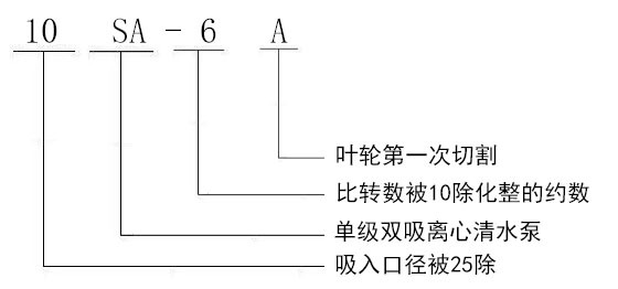
Model Description
Example: 10SA-6A;
10-The suction diameter is divided by 25 (the suction diameter is 250mm);
SA-single-stage double-suction centrifugal clean water pump;
6-divisor of specific revolutions divided by 10;
A- impeller outer diameter change.
-
Flow range: Q = 90~6300 m3/h
Head range: H = 9.5~305m
Conveying temperature:-20 ℃ to 80 ℃
Inlet pressure: 0.6MPa
Sealing form: packing seal, mechanical seal
Water pump material: HT200, HT250, QT600, ZG, 304, 316, 316L, 317L, 904L, CD4-MCu, etc


-
-
Assembly, disassembly and installation
Assembly and disassembly
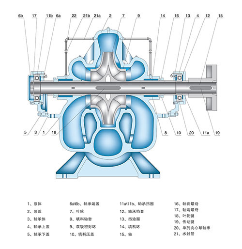
1. Assemble rotor components: sequentially install the impeller, shaft sleeve, shaft sleeve nut, packing sleeve, packing ring, packing gland, water retaining ring and bearing components on the pump shaft, and install the double-suction sealing ring, and then install the coupling.
2. Install the rotor parts on the pump body, adjust the axial position of the impeller to the middle of the double-suction sealing ring on both sides to fix it, and fasten the bearing body gland with the fixing screw.
3. Install the filler, put the paper pad on the middle opening surface, cover the pump cover and tighten the screw tail column pin, tighten the pump cover nut, and finally install the grave material gland. But do not press the packing too tight, packing too tight will make the sleeve heat, power consumption is larger, do not press too loose, too loose will make the liquid leakage, pump efficiency is reduced.
After the assembly is completed, rotate the pump shaft by hand without rubbing. The rotation is relatively smooth and even. Disassembly can be carried out in the reverse order of the above assembly.
Installation
1, check the water pump and motor should be no damage.
2. The installation height of the water pump, plus the hydraulic loss of the suction pipeline and its speed energy, shall not be greater than the allowable suction vacuum height value specified in the sample. The size of the foundation shall be in accordance with the installation size of the pump unit.
3. Installation order
① Put the water pump on the concrete foundation with anchor bolts, adjust the level by adjusting the wedge-shaped cushion block between them, and tighten the anchor bolts appropriately to prevent walking.
② Concrete shall be poured after the foundation and pump foot.
③ After the concrete is dry, tighten the anchor bolts and recheck the levelness of the water pump.
④ Correct the concentricity of the motor shaft and the water pump shaft. Make the two axes in a straight line, the coaxiality tolerance on the outer circle of the two axes is 0.1mm, and the unevenness tolerance of the end face clearance along the circumference is 0.3mm (check it again after connecting the inlet and outlet water pipes and trial operation, and still meet the above requirements).
⑤ After checking that the steering direction of the motor is consistent with that of the water pump, install the coupling and the connecting pin.
4. The inlet and outlet pipes shall be supported by another bracket, and the pump body shall not be supported.
5. The junction between the water pump and the pipeline should ensure good air tightness, especially the water inlet pipeline, which must ensure strict air leakage, and there should be no possibility of air storage on the device.
6. If the water pump is installed above the inlet water level, the bottom valve can be installed in order to start the pump. The method of vacuum water diversion can also be used.
7. After the water pump and the outlet pipeline, gate valves and check valves are generally required (those with a lift of less than 20 meters are not required), and the check valves are installed behind the gate valves. The installation method mentioned above refers to the water pump unit without a common base.
Install the pump with common base, adjust the level of the unit by adjusting the wedge between the base and the concrete foundation. Concrete is then poured in. The installation principle and requirements, and not with a common base unit of the same.
Starting, stopping and running
1. Start and stop
Before starting, rotate the pump rotor, should be smooth and even.
② Close the outlet gate valve and inject it into the pump (if there is no bottom valve, use the vacuum pump to evacuate and divert water) to ensure that the pump is full of water. No air nest.
③ If the pump is equipped with a vacuum gauge or pressure gauge. To turn off the spin base connected to the pump and restart the motor. Wait until the speed is normal and then open; Then gradually open the outlet gate valve. If the flow is too large, the gate valve can be properly closed for adjustment. On the contrary, the flow rate is too small. Open the gate valve wide.
④ Tighten the compression nut on the packing gland evenly to make the liquid leak out in drops. At the same time, pay attention to the temperature rise at the filling cavity.
⑤ When the pump is stopped. Close the cock of the vacuum gauge and pressure gauge and the gate valve on the outlet pipe first. Then turn off the power to the motor. If the temperature of the environment is low, the square screw plug at the lower part of the pump body should be opened. Remove? Water. So as not to freeze and crack. ⑥ When long-term use is stopped. The water pump should be disassembled to dry the water from the other parts. Coat the processed surface with anti-rust oil and keep it well.
2-Operation
The maximum temperature of the water pump bearing should not exceed 75°C.
② The amount of calcium-based butter used for lubricating the bearing should be 1/3 to 1/2 of the bearing body space.
③ The packing gland can be properly pressed when the packing is worn. If excessive wear should be replaced.
(4) Regular inspection equipment department. Caution
⑤ During operation. If you find noise or other abnormal sounds, stop the car immediately. Check the cause. to be eliminated.
⑥ Do not arbitrarily increase the speed of the pump. but can reduce the speed of use. If the rated speed of this type of pump is n, the flow rate is q, the head is h, the shaft power is n, and the reduced speed is n1. Flow after deceleration. Head. The shaft power is Q1, H1 and N1. their mutual relations. The following formula can be used for conversion: Q1 =(n1/n)Q H1 =(n1/n)2H N1 =(n1/n)3N
Customer Case
Product Consulting
If you are interested in our products, please leave your email, we will contact you as soon as possible, thank you!


Hunan Sanchang Pump Co., Ltd.
| Email: | info@sanchangpump.net |
| Hotline: | +86 181 4266 2779 |
| +86 193 1300 1794 | |
| Mobile/Wechat/WhatsApp: | +86 181 4266 2779 |
| Address: | No.517,Xiangfu Road, Yuhua |
| District, Changsha City | |
| Hunan Province, P.R.C |
