
Recommend Products
Contact Us
| Email: | info@sanchangpump.net |
| Hotline: | +86 181 4266 2779 |
| +86 193 1300 1794 | |
|
Wechat: |
+86 181 4266 2779 |
|
WhatsApp: |
+86 181 4266 2779 |
| Address: | No.517,Xiangfu Road |
| Yuhua District, | |
| Changsha City | |
| Hunan Province, P.R.C |

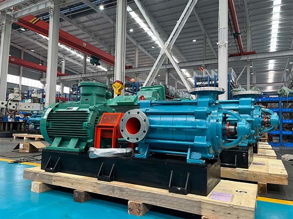
MD Wear-resistant Multistage Centrifugal Pump for Mining
Classification:
BB4 Multistage Centrifugal Pump
MD type wear-resistant multistage centrifugal pump for mine
Mining industry
Multi-stage pump for mine
MD type wear-resistant multistage centrifugal pump for mine
Key words:
water pump
Head Range: 50~2000m
Medium Temperature: 0℃~80℃
Allowable Inlet Pressure: 0.6MPa
Shaft Seal: packing seal, mechanical seal
Available Materials: HT200, HT250, QT600, ZG, 304, 316, 316L, 317L, 904L, CD4-MCu, etc
Hotline:
- Product Description
- Performance Parameter
- Installation Drawings
- Installation And Use
- Faults And Solutions
-
- Commodity name: MD Wear-resistant Multistage Centrifugal Pump for Mining
Flow Range: 3.75~1400m3/h<br>Head Range: 50~2000m<br>Medium Temperature: 0℃~80℃<br>Allowable Inlet Pressure: 0.6MPa<br>Shaft Seal: packing seal, mechanical seal<br>Available Materials: HT200, HT250, QT600, ZG, 304, 316, 316L, 317L, 904L, CD4-MCu, etc</br></br></br></br></br>
MD type Wear-resistant Pump is horizontal single-suction sectional-type multistage centrifugal pump developed with high-efficiency energy-saving hydraulic profiles specifically for mining industry high-pressure service. It features high efficiency, wide performance range, stable safe operation, low noise, long service life and convenient installation & maintenance.Designed for conveying neutral mine water and similar wastewater containing solid particles ≤15% by weight, particle size ≤0.5 mm and medium temperature ≤80℃. Widely applied in steel plants, mine drainage and wastewater transportation projects.
Model Description:
Example: MD280-43 × 5
MD —— Wear-resistant Multistage Centrifugal Pump for Mining
280 —— Design rated flow: 280m³/h
43 —— Single-stage design head: 43 m
5 —— Total number of pump stages
Rotation Direction:
Clockwise when viewing from motor end towards pump.
Material of Wetted Components:
All wetted parts are available in wear-resistant ductile iron, cast steel and stainless steel grades: 304, 316, 316L, 2205, 2507 and so on.
Supply Scope of Complete Set:
The package consists of pump, electric motor and base frame; either shared common base or independent pump base is optional. Manufacturer supplies auxiliary fittings (discharge reducer, gate valve, foot valve, check valve) and spare parts (impeller, wear ring, diffuser sleeve, balance disc, shaft sleeve).
Structure Description:
D, DG, MD, DF and DY type consist of four core assemblies: stationary casing assembly, rotor assembly, bearing assembly and shaft seal assembly.
1. Stationary Parts
Consisting of suction casing, middle casing, discharge casing and diffusers; all segments are clamped tightly by through tie bolts to form pump working chambers.D type: Horizontal suction nozzle, vertically upward discharge nozzle.DG type: Both suction and discharge nozzles point vertically upward.MD, DF, DY type: Standard horizontal suction with vertical discharge; vertical suction & discharge design available upon special order.
2. Rotor Assembly
Composed of pump shaft, impellers, balance disc and replaceable shaft sleeves. The shaft transmits torque to drive impeller operation; balance disc counteracts axial thrust; replaceable shaft sleeves protect pump shaft against abrasion.
3. Bearing Assembly
Made up of bearing housing, bearings and bearing gland.
85‑67, 155‑67, 600‑60 adopt sleeve bearings with oil bath lubrication; rolling bearing structure is optional for 85‑67 and 155‑67.All other models use rolling bearings with grease lubrication.
4. Shaft Seal
Standard configuration is soft packing seal composed of stuffing box body, packing and water slinger mounted on suction casing and end cover. Pressurized sealing water is fed into stuffing box for water sealing, cooling and lubrication.D type: Sealing water taken from pump internal high-pressure liquid.DG, MD, DF, DY type: Sealing water sourced from internal process liquid or external service water; mechanical seal is commonly selected as alternative for these four series.
5. Drive Arrangement
The pump is directly driven by prime mover via flexible coupling; rotation is clockwise viewed from prime mover side.
-
Flow Range: 3.75~1400m3/h
Head Range: 50~2000m
Medium Temperature: 0℃~80℃
Allowable Inlet Pressure: 0.6MPa
Shaft Seal: packing seal, mechanical seal
Available Materials: HT200、HT250、QT600、ZG、304、316、316L、317L、904L、CD4-MCu等
-
Outline Installation Drawing of MD Wear-resistant Multistage Centrifugal Pump

-
Installation Specification of MD Wear-resistant Multistage Centrifugal Pump
Pre-installation Preparation
1. Confirm installation location: Select a solid mounting position convenient for operation, maintenance and overhaul.
2. Locate priming port: The priming port shall be arranged on suction pipeline approximately 20 cm away from the pump to prevent backflow-induced fluctuation of impeller rotating speed.
3. Prepare suction pipeline: Inspect pipes and flange joints to remove foreign debris and rust.
4. Prepare power supply and cables: Select qualified cables complying with the pump’s electrical specifications.
Installation Procedures
1. Component assembly: Assemble all parts per drawing and manual requirements, confirm positions of discharge nozzle, vent port and lubrication fittings.
2. Pump positioning: Place the pump on the preset site with its base fully and evenly seated perpendicular to the ground.
3. Piping connection: Connect suction and discharge pipelines; flanges shall be parallel and horizontal without twist or deformation.
4. Cable wiring: Complete wiring strictly in accordance with electrical schematic with standardized routing.
5. Pump priming: Open suction stop valve and fill clean water (or designated priming liquid) into pump casing to eliminate abnormal vibration and noise.
6. Operational adjustment: Adjust frequency converter or reducer as required to ensure stable motor operation and proper flow velocity.
Post-installation Inspection
1. Overall pump inspection: Verify the pump base is level and vertical.
2. Pipeline inspection: Check tightness of all flange connections and eliminate abnormal noise.
3. Rotation test: Switch on power to check smooth motor rotation, abnormal sound and liquid leakage.
4. System pressure test: Record valve switching status and flow data via intelligent instruments; monitor unusual noise, vibration or overheating and troubleshoot immediately if any fault occurs.
5. Cable inspection: Confirm correct wiring and intact cables complying with installation standards.
The above detailed installation steps shall be followed to guarantee reliable pump operation for production and domestic service.
-
Common Faults & Remedies of MD Wear-resistant Multistage Centrifugal Pump
Fault 1: Pump fails to draw water; sharp fluctuation of pointers on pressure gauge and vacuum gauge
Causes
Insufficient priming water filled into pump
Air leakage at joints of pipeline and instruments
Excessive suction lift
Remedies
Check foot valve for leakage and refill priming water sufficiently
Fasten leaking connections
Reduce suction lift height
Fault 2: No water intake; vacuum gauge shows ultrahigh vacuum reading
Causes
Foot valve closed or clogged
Excessive resistance on suction pipeline
Strainer blocked
Remedies
Inspect and repair foot valve
Modify suction pipeline
Clean up the strainer
Fault 3: Pressure gauge reads pressure yet no liquid discharged
Causes
Overhigh resistance on discharge pipeline
Wrong motor rotation direction
Closed discharge valve
Blocked impeller
Remedies
Inspect or shorten discharge piping
Check motor and swap two phases of power supply
Open discharge valve fully
Clear foreign contaminants inside impeller
Fault 4: Actual flow lower than designed rated flow
Causes
Air ingress into pump casing
Reduced liquid level leads to insufficient submergence depth
Impeller clogged with foreign materials
Severe abrasion of rotary assembly parts
Remedies
Locate and eliminate all air leakage points
Extend suction pipe to increase submergence depth
Dismantle pump and remove blockages
Replace worn wear rings
Fault 5: Excessive power consumption of pump unit
Causes
Over-tightened packing gland with overheating
Excessive operating flow rate
Rubbing contact between rotating assembly and pump casing
Worn pump bearings
Bent pump shaft
Remedies
Loosen packing gland appropriately
Throttle gate valve to reduce flow
Adjust position of rotating parts and casing to eliminate friction
Replace defective bearings
Straighten or renew bent pump shaft
Fault 6: Abnormally high pump vibration
Causes
Partial blockage on impeller
Damaged impeller
Undersized operating flow
Misalignment between pump shaft and motor shaft
Failed bearings
Air entrainment resulting in cavitation
Remedies
Dismantle pump and remove obstructions on impeller
Install new impeller
Slightly open discharge valve to raise flow
Perform precision shaft alignment
Modify suction layout to optimize suction condition
Previous Page
Customer Case
Product Consulting
If you are interested in our products, please leave your email, we will contact you as soon as possible, thank you!


Hunan Sanchang Pump Co., Ltd.
| Email: | info@sanchangpump.net |
| Hotline: | +86 181 4266 2779 |
| +86 193 1300 1794 | |
| Mobile/Wechat/WhatsApp: | +86 181 4266 2779 |
| Address: | No.517,Xiangfu Road, Yuhua |
| District, Changsha City | |
| Hunan Province, P.R.C |
