
Products
Recommend Products
Contact Us
| Email: | info@sanchangpump.net |
| Hotline: | +86 181 4266 2779 |
| +86 193 1300 1794 | |
|
Wechat: |
+86 181 4266 2779 |
|
WhatsApp: |
+86 181 4266 2779 |
| Address: | No.517,Xiangfu Road |
| Yuhua District, | |
| Changsha City | |
| Hunan Province, P.R.C |

ZE Type OH2 Petrochemical Process Pump
Classification:
API 610 Pump
Power Plant
Metallurgical
Key words:
Petrochemical Process Pump
Process Pump
OH2 Pump


Hotline:
- Product Description
- Performance Parameters
- Installation Drawings
- Installation and Operation
- Faults and Solutions
-
- Commodity name: ZE Type OH2 Petrochemical Process Pump
Flow Range: 5.5~2600 m3/h</br> Head Range: 16~250 m</br> Fluid Temperature: -80 ℃ ~ 450 ℃</br> Inlet Pressure: ~ 2.5 MPa</br> Shaft Seal: packing seal, mechanical seal</br> Available Materials: HT200, HT250, QT600, ZG, 304, 316, 316L, 317L, 904L, CD4-MCu, etc
Product Description
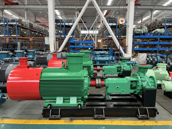
The ZE type petrochemical process pump is designed in compliance with API610, API682 and VDMA24297 (Heavy Duty) standards. It is a single-stage, single-suction overhung volute pump with centerline supported pump casing, featuring axial suction and radial discharge. Axial thrust is hydraulically balanced by front and rear wear rings and balance holes.
Cartridge type single or double balanced mechanical seals are available, equipped with cooling, flushing or seal liquid systems. The seal piping system is designed per API standards. The maximum working pressure is 5.0 MPa. Suction and discharge flanges can be manufactured in accordance with GB, DIN and ANSI standards.
Overview
The ZE type petrochemical process pump is applicable for conveying inorganic acids, organic acids such as sulfuric acid, nitric acid, hydrochloric acid and phosphoric acid of varying temperatures and concentrations; alkaline solutions including sodium hydroxide and sodium carbonate; various salt solutions, liquid petrochemical products, organic compounds and other corrosive fluids.
It is widely used in oil refineries, petrochemical industry, coal chemical projects, cryogenic engineering, papermaking, sugar manufacturing, waterworks, seawater desalination plants, power plants, environmental protection projects and marine industry.
The pump rotates clockwise when viewed from the motor end.
Material Selection
A full range of corrosion-resistant materials are optional, including 303, 305, 306, 307, 316, 316L, 904, 904L, 804, ECR alloy, NiCr alloy, Hastelloy, CD-4MnCu and titanium alloy, which can meet the requirements of various media mentioned above. Please provide detailed information of the conveyed medium when placing orders.
Structural Features
1. The process pump adopts standard piping designed to API specifications. Three types of impellers are available: closed, semi-open and open, suitable for clean media, media with solid particles and media containing a small amount of gas, as well as high-temperature, low-temperature and highly corrosive fluids. The impeller is fitted with balance holes and corrosion-resistant wear rings to balance axial thrust.
2. The pump casing and bearing bracket are connected via an intermediate section. Different materials can be selected for the intermediate section according to working conditions, so as to prevent severe corrosion of the bearing bracket and bearings when handling highly corrosive media. A water cooling chamber is arranged on the intermediate section. Circulating cooling water is fed into the chamber to isolate high temperature from being transferred to the bearings.
3. Available seal types include gland packing seal, single/double mechanical seal and cartridge single mechanical seal. Seals can be selected from API682 standard options based on on-site conditions and user requirements for cooling and flushing.
4. The bearing bracket is designed with three heat dissipation structures: air cooling fins, cooling fan and water cooling chamber for optional selection. Bearings are lubricated by oil ring splash lubrication. The lubricating oil in the oil sump is cooled by circulating water in the water cooling chamber to keep bearings operating under normal temperature.
5. Two support structures are adopted: centerline support and foot support, selected according to medium temperature, pressure and other operating parameters.
6. The suction and discharge flanges have the same pressure rating.
Applications
This pump is suitable for conveying clean or particle-laden liquids, low or high temperature liquids, neutral or corrosive liquids. It can handle media that are low/high temperature, neutral/corrosive, clean/solid particle-containing, toxic, flammable and explosive.
Main application fields: oil refineries, petrochemical industry, coal chemical industry, power plants, pulp & paper industry, pharmaceutical industry, general industrial processes and offshore industry. It delivers a wide performance range.
Model Description
Example: ZE25-200C
ZE -- Petrochemical Process Pump
25 -- Discharge diameter (mm)
200 -- Nominal impeller diameter (mm)
C -- Code for impeller trimming; marked in sequence as A, B, C, etc.
-
Flow Range: 5.5~2600 m3/h
Head Range: 16~250 m
Fluid Temperature: -80 ℃ ~ 450 ℃
Inlet Pressure: ~ 2.5 MPa
Shaft Seal: packing seal, mechanical seal
Available Materials: HT200, HT250, QT600, ZG, 304, 316, 316L, 317L, 904L, CD4-MCu, etc
-
-
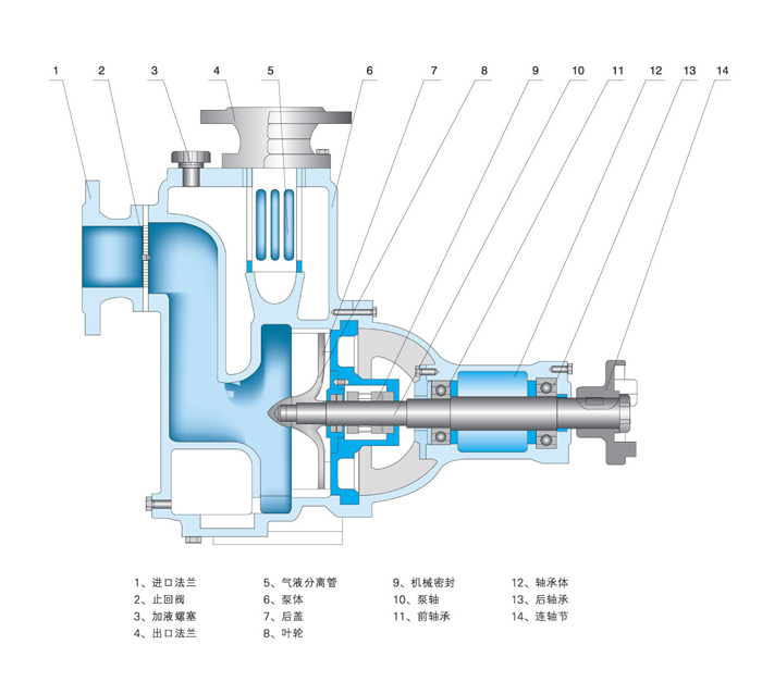
1. Proper installation inspection and alignment are essential for the normal operation and service life of chemical pumps. Alignment shall be completed before installation.
2. Ensure the pump operates above the required net positive suction head (NPSH). The suction lift shall be determined according to the pump's NPSH characteristics.
3. Separate supports shall be fitted for suction and discharge pipelines. The pump casing shall not bear the weight of pipelines.
4. The pump shall be installed at a location convenient for routine inspection and maintenance.
5.Installation Procedures
① Place the pump unit on the foundation pre-embedded with anchor bolts. Use paired wedge shims between the base and foundation for levelling and alignment.
② Disconnect the coupling. Place a level gauge on the pump shaft or base respectively. Adjust the wedge shims to level the entire unit, then tighten the anchor bolts to prevent displacement.
③ Pour concrete into the anchor bolt holes and the gap around the base.
④ After the concrete is fully cured, retighten the anchor bolts and recheck the levelness of the pump shaft.
⑤ Connect all pipelines and confirm the correct rotation direction of the motor, then re-engage the coupling. Recheck shaft concentricity: the radial runout of the coupling outer circle (top, bottom, left and right) shall not exceed 0.1 mm; the maximum deviation of the end face gap around the two couplings shall not exceed 0.3 mm.
⑥ Conduct a full inspection after 3 to 4 hours of trial operation. The installation is deemed qualified if no abnormalities are found.
-
Causes and Solutions for Pump Failing to Deliver Liquid During Operation
1. Insufficient liquid inside the pump cavity (air not fully vented).Solution: Refill liquid until the pump cavity is completely full.
2. Incorrect rotation direction upon start-up.Solution: Check the running direction of the matched motor.
3. Excessively low rotating speed after start-up.Solution: Stop the pump to inspect the motor speed and replace the motor with appropriate power and rated speed.
4. Clogged strainer at the inlet.Solution: Inspect the strainer and remove debris.
5. Actual suction lift exceeds the rated value, resulting in vacuum in the liquid tank.Solution: Reduce the suction lift and check the pressure of the liquid tank.
Causes and Solutions for Intermittent Liquid Discharge
1. Air leakage from the suction pipeline.Solution: Inspect pipe joints and gland packing for air leakage.
2. Residual air inside the suction line after priming.Solution: Re-prime the pump.
3. Inlet blocked by foreign matters.Solution: Shut down the pump and clear the blockage.
4. Large amount of air drawn into the inlet.Solution: Check for vortex at the suction port and verify the liquid submergence depth.
Causes and Solutions for Pump Vibration
1. Excessive misalignment between pump shaft and motor shaft.Solution: Realign the two shafts.
2. Excessive suction lift leading to cavitation.Solution: Lower the pump installation height.
3. Mechanical friction inside the pump.Solution: Locate the worn parts and carry out maintenance.
Previous Page
Next Page
Customer Case
Send Inquiry
If you are interested in our products, please leave us a message and we will reply to you as soon as possible, thank you!



Hunan Sanchang Pump Co., Ltd.
| Email: | info@sanchangpump.net |
| Hotline: | +86 181 4266 2779 |
| +86 193 1300 1794 | |
| Mobile/Wechat/WhatsApp: | +86 181 4266 2779 |
| Address: | No.517,Xiangfu Road, Yuhua |
| District, Changsha City | |
| Hunan Province, P.R.C |
