
Products
Recommend Products
Contact Us
| Email: | info@sanchangpump.net |
| Hotline: | +86 181 4266 2779 |
| +86 193 1300 1794 | |
|
Wechat: |
+86 181 4266 2779 |
|
WhatsApp: |
+86 181 4266 2779 |
| Address: | No.517,Xiangfu Road |
| Yuhua District, | |
| Changsha City | |
| Hunan Province, P.R.C |

High Efficiency Horizontal Double-suction Split casing Pump
Classification:
Split Case Centrifugal Pump
Salt Chemical
Water Conservancy
Key words:
Split-case Pump
Single-stage Double-suction Pump
Horizontal Centrifugal Pump


Hotline:
- Product Description
- Performance Parameters
- Installation Drawings
- Installation and Operation
- Faults and Solutions
-
- Commodity name: High Efficiency Horizontal Double-suction Split casing Pump
Flow Range: 160 ~ 18000 m3/h</br> Head Range: 10 ~ 280m</br> Fluid Temperature: -20 ~ 80 ℃</br> Inlet Pressure: ≤ 0.6 MPa</br> Shaft Seal: packing seal, mechanical seal</br> Available Materials: HT200, HT250, QT600, ZG, 304, 316, 316L, 317L, 904L, CD4-MCu, etc</br></br></br>
S, SH horizontal single-stage double-suction split-case agricultural centrifugal pumps are new high-efficiency energy-saving pumps.
Compared with SA and traditional SH pumps, they have broader application ranges.
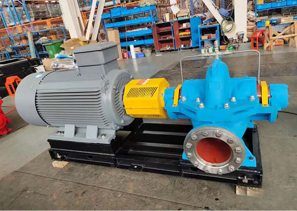
Designed per industry standards, the series features high serialization, standardization and interchangeability.
With optimized structures and upgraded materials, the pumps run stably with high safety and reliability, and can transport multiple types of medium.
I. Application & Conveyable Media
S,SH type pumps are applicable for clean water transportation. They can also convey liquids with similar physical and chemical properties to water.
Main Application Scenarios:
- Urban water supply and drainage
- Water intake and pressurization for power stations
- Industrial process system water pressurization
- Farmland irrigation and drainage
- Water conservancy projects
- Petrochemical engineering
II. Structure Description
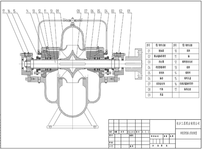
- Suction and discharge nozzles are located below the pump shaft centerline. The nozzles are perpendicular to the shaft axis.
- No pipeline disassembly or motor removal is required for daily maintenance.
- Standard rotation: clockwise when viewed from the drive end.
- Custom rotation: counterclockwise is available on request.
Main Components: Pump casing, pump cover, impeller, shaft, double-suction wear ring, shaft sleeve
Core Part Materials:
- Pump shaft: high-quality carbon steel
- Other major parts: cast iron, cast steel, stainless steel
Pump Casing & Pump Cover
- Form a closed working chamber for the impeller
- Inlet and discharge flanges reserve tapped holes for vacuum gauges and pressure gauges
- Threaded drain holes are equipped at the bottom of flange parts
Impeller
- Passed professional static balance test
- Fixed on the shaft by bilateral shaft sleeves and sleeve nuts
- Axial position can be adjusted via sleeve nuts
- Symmetrical blades and double-sided water intake balance axial thrust automatically
Bearing Configuration
- Radial ball bearings installed at both pump ends
- Adopt grease lubrication for stable operation
Wear Ring
Effectively reduces liquid backflow from the pressure chamber to the suction chamber.
Driving Mode
- Standard drive: Motor drive via flexible coupling
- Alternative drive: Internal combustion engine drive for special scenarios
Shaft Seal System
- Standard configuration: soft packing seal
- Optional configuration: mechanical seal
- Built-in packing ring prevents air ingress
- Packing ring cools and lubricates the seal chamber
- High-pressure liquid forms water seal through pump cover trapezoidal groove during operation
III. Material Description
Multiple optional materials meet diverse working conditions:
Copper, cast iron, ductile iron, 316 stainless steel, 416 stainless steel, duplex steel, Hastelloy, Monel, titanium alloy, Alloy 20 and more.
IV. Model Description
Example: 500 S/SH 35A
- 500 —— Pump inlet diameter, 500 mm
- S/SH —— Single-stage, double-suction, split-case clean water centrifugal pump
- 35 —— Design head, 35 m
- A —— First trimming of the impeller
-
Flow Range: 160 ~ 18000 m3/h
Head Range: 10 ~ 280m
Fluid Temperature: -20 ~ 80 ℃
Inlet Pressure: ≤ 0.6 MPa
Shaft Seal: packing seal, mechanical seal
Available Materials: HT200, HT250, QT600, ZG, 304, 316, 316L, 317L, 904L, CD4-MCu, etc
-
-
Installation
1. Inspect the S-type split-case pump and motor to ensure no damage.
2. The sum of the pump installation height, hydraulic loss of the suction pipeline and velocity head shall not exceed the allowable suction vacuum height specified in the product datasheet. The foundation dimensions shall match the overall size of the pump unit.
3. Installation Procedures
① Place the pump on the concrete foundation with pre-embedded anchor bolts. Level the unit by adjusting wedge shims, and slightly tighten the anchor bolts to prevent displacement.
② Pour concrete between the foundation and pump base.
③ After the concrete is fully cured, tighten the anchor bolts completely and recheck the levelness of the S-type split-case pump.
④ Align the motor shaft and pump shaft to keep them collinear. The coaxiality tolerance on the outer circle of the two shafts is 0.1 mm, and the unevenness tolerance of the end clearance along the circumference is 0.3 mm. Recheck and verify compliance after connecting pipelines and conducting trial operation.
⑤ Confirm the motor rotation direction is consistent with the pump, then install the coupling and connecting pins.
4. Separate supports shall be fitted for suction and discharge pipelines. Do not let the pump casing bear the weight of pipelines.
5. Ensure excellent airtightness at joints between the pump and pipelines. The suction pipeline in particular must be completely airtight without trapped air.
6. If the pump is installed above the water level, fit a foot valve for priming. Vacuum water diversion is also an alternative method.
7. A gate valve and a check valve are generally installed on the discharge pipeline. The check valve can be omitted if the head is less than 20 meters, and it shall be mounted behind the gate valve.
The above instructions apply to pump units without a common base frame.
For units equipped with a common base frame, level the unit by adjusting wedge shims between the base frame and concrete foundation, then pour concrete in the gaps. All installation principles and requirements remain the same.
Start-up, Shutdown and Operation
1. Start-up and Shutdown
① Rotate the pump rotor manually before start-up; it shall turn smoothly and freely.
② Close the discharge gate valve and fill the pump with water. Use a vacuum pump for water diversion if no foot valve is installed. Ensure the pump is fully filled with water and free of trapped air.
③ Close the cocks connected to the vacuum gauge and pressure gauge before starting the motor. Open the cocks after the motor runs at rated speed, then gradually open the discharge gate valve. Regulate the flow rate by adjusting the valve opening.
④ Tighten the nuts on the packing gland evenly to allow liquid to drip slowly. Monitor the temperature rise of the packing chamber meanwhile.
⑤ Before shutdown, close the gauge cocks and discharge gate valve first, then cut off the motor power. In low-temperature environments, remove the square plug at the pump bottom and drain residual water to prevent the pump from cracking due to freezing.
⑥ For long-term decommissioning, disassemble the pump, wipe off all water on components, and apply anti-rust oil on machined surfaces for storage.
2. Operation Rules
① The maximum operating temperature of pump bearings shall not exceed 75℃.
② Calcium-based grease for bearing lubrication shall fill 1/3 ~ 1/2 of the bearing housing cavity.
③ Retighten the packing gland appropriately when the packing wears. Replace the packing if it is severely worn.
④ Inspect coupling components regularly and keep track of temperature rise of motor bearings.
⑤ Stop the pump immediately if abnormal noise occurs during operation. Identify and eliminate faults before restarting.
⑥ The rotating speed of the water pump shall not be increased arbitrarily, but the rotating speed can be reduced. For example, the rated rotating speed of the pump is N, the flow rate is Q, the lift is H, the shaft power is N, the rotating speed is reduced to n1, and the flow rate, lift and shaft power after speed reduction are Q1, H1 and N1 respectively. The interrelationship can be converted by the following formula.
Q1 = (N1/N) Q h1 = (N1/n)2 h N1 = (N1/n)3 N
Assembly and disassembly
1. Rotor Assembly: Mount the impeller, shaft sleeve, shaft sleeve nut, packing sleeve, packing ring, packing gland, water deflector and bearing assembly onto the pump shaft in sequence. Fit the double-suction wear ring, then install the coupling.
2. Mount the assembled rotor onto the pump casing. Adjust the axial position of the impeller to the middle of the double-suction wear ring and secure it. Fasten the bearing housing cover with set screws.
3. Install the packing, place the paper gasket on the split surface, fit the pump cover and drive in the taper pins, then tighten the pump cover nuts. Finally, install the packing gland.
Do not over-tighten the packing, as it will cause shaft sleeve overheating and increased power consumption. Loose packing will lead to severe liquid leakage and reduced pump efficiency.
After assembly, rotate the pump shaft manually. It shall operate smoothly without friction or collision.
Disassembly shall be performed in the reverse order of assembly.
Customer Case
Send Inquiry
If you are interested in our products, please leave us a message and we will reply to you as soon as possible, thank you!



Hunan Sanchang Pump Co., Ltd.
| Email: | info@sanchangpump.net |
| Hotline: | +86 181 4266 2779 |
| +86 193 1300 1794 | |
| Mobile/Wechat/WhatsApp: | +86 181 4266 2779 |
| Address: | No.517,Xiangfu Road, Yuhua |
| District, Changsha City | |
| Hunan Province, P.R.C |
