
Products
Recommend Products
Contact Us
| Email: | info@sanchangpump.net |
| Hotline: | +86 181 4266 2779 |
| +86 193 1300 1794 | |
|
Wechat: |
+86 181 4266 2779 |
|
WhatsApp: |
+86 181 4266 2779 |
| Address: | No.517,Xiangfu Road |
| Yuhua District, | |
| Changsha City | |
| Hunan Province, P.R.C |

IJ Type Corrosion-resistant Chemical Centrifugal Pump
Classification:
End Suction Centrifugal Pump
Metallurgical
Power Plant
Key words:
Chemical Pump
Corrosion-resistant Pump
Centrifugal Pump


Hotline:
- Product Description
- Performance Parameters
- Installation Drawings
- Installation and Operation
- Faults and Solutions
-
- Commodity name: IJ Type Corrosion-resistant Chemical Centrifugal Pump
Flow Range: 6~1200 m3/h</br> Head Range: 5~80 m</br> Fluid Temperature: -80 ℃ ~ 450 ℃</br> Inlet Pressure: 16~250m</br> Shaft Seal: packing seal, mechanical seal</br> Available Materials: HT200, HT250, QT600, ZG, 304, 316, 316L, 317L, 904L, CD4-MCu, etc</br></br></br></br>
IJ type single-stage single-suction overhung chemical centrifugal pump is a newly optimized product developed on the basis of the IH series pumps, adopting foreign advanced technologies and combining practical application feedback from end users. Its rated performance and installation dimensions comply with ISO 2858 (equivalent to ISO 2858-1975), and manufacturing technical requirements conform to ISO 5199. It is mainly used to convey slurry with solid content below 50% and media containing crystalline impurities in chemical processes. It belongs to the same category as the nationally promoted IH type pump.
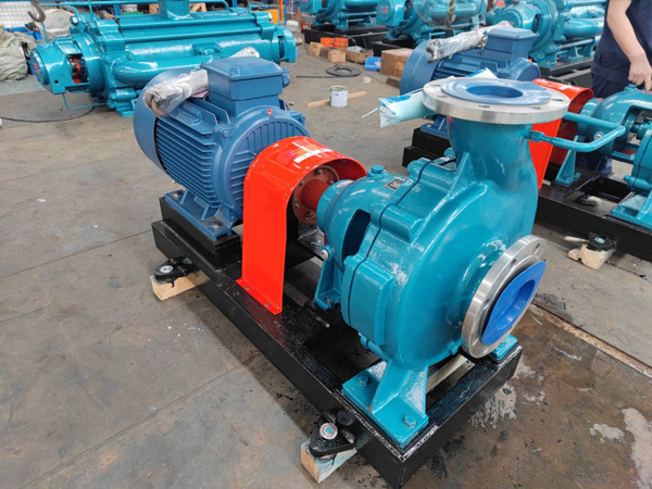
Rotation Direction
It rotates clockwise when viewed from the drive end, opposite to the rotation direction of F-type pumps.
Main Applications
- Alkali industry: Ammonia brine and mother liquor for soda ash and combined soda production; normal-temperature caustic alkali, chlorine products, chlorate and hypochlorite for chlor-alkali production.
- Non-ferrous metallurgy: Electrolyte for copper and nickel electrolysis, acid mist liquid for cobalt production, ore slurry for zinc production, ammonium vanadate for vanadium production, acid and thiourea solution for gold production.
- Iron and steel industry: Electroplating, pickling and waste acid treatment.
- Acid-making industry: Nitric acid, sulfuric acid, hydrochloric acid, phosphoric acid, acetic acid, etc.
- Petrochemical industry: Petroleum refining, acetaldehyde and alkylbenzene production.
- Synthetic fiber & plastics industry: Production of polyester and polyvinyl chloride; textile and printing & dyeing industries.
- Papermaking industry: Conveyance of pulp cooking liquor and bleaching liquor.
- Fertilizer industry: Production of urea and ammonium nitrate.
- Pharmaceutical industry: Manufacturing of medicines and pesticides.
- Environmental protection: Conveyance of acid mist liquid.
Structural Advantages Compared with IH Pumps
1. Shortened overhang length of the impeller and increased shaft diameter.
2. Volute with asymmetric cross-section; no wear ring on pump casing.
3. Equipped with three inlet bearings.
4. Adopts new-type seals, equivalent to advanced foreign double mechanical seals or gland packing seals.
The above structural design brings the following superiorities
1. Capable of conveying high-viscosity media and media with solid particles, with higher efficiency than IH pumps under such working conditions.
2. The asymmetric volute reduces fluid impact loss and downsizes the pump casing.
3. Enhanced shaft strength and reduced rotor deflection ensure stable operation and longer service life of seals.
4. Integrated impeller nut and impeller optimizes inlet flow condition and improves cavitation resistance.
5. Advanced shaft sealing structure delivers better sealing performance and lowers leakage rate.
6. Clearance adjustment can be realized without removing the pump casing and impeller, which cuts maintenance time and costs.
Structural Features
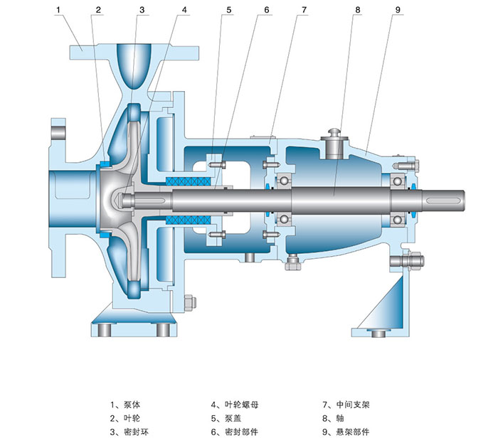
The pump features axial suction and radial discharge. The discharge port and shaft are arranged on the same vertical plane. Integral support feet are cast on the pump body for direct mounting on the base. The pump cover is fixed to the bearing bracket via spigot joint and clamped tightly between the pump body and bearing bracket.
For maintenance, simply remove the connecting nuts between the bearing bracket and pump body, then the rotating assembly can be pulled out without detaching the inlet and outlet pipelines. This is a widely adopted structure for chemical pumps worldwide.
For large-size pumps, an intermediate extension piece is installed between the coupling and motor shaft. During maintenance, remove the intermediate piece to extract the rotor assembly from the pump body, while the motor can remain in place.
-
Flow Range: 6~1200 m3/h
Head Range: 5~80 m
Fluid Temperature: -80 ℃ ~ 450 ℃
Inlet Pressure: 16~250m
Shaft Seal: packing seal, mechanical seal
Available Materials: HT200, HT250, QT600, ZG, 304, 316, 316L, 317L, 904L, CD4-MCu, etc
-
-
Installation Guidelines for IJ Type Corrosion-resistant Chemical Centrifugal Pump
1. Proper inspection and alignment prior to installation are vital to the normal operation and service life of chemical pumps.
2. Ensure the pump operates within the allowable net positive suction head (NPSH). The suction lift shall be determined according to the pump's NPSH performance parameters.
3. Separate supports shall be installed for suction and discharge pipelines. The pump casing shall not bear the load of pipelines.
4. Locate the pump at a position convenient for routine inspection and maintenance.
5. Installation Procedures
① Place the pump unit on the foundation with pre-embedded anchor bolts. Use paired wedge shims between the base and foundation for alignment.
② Disconnect the coupling. Place a level gauge on the pump shaft or base. Adjust the wedge shims to level the unit, then tighten the anchor bolts to prevent displacement.
③ Pour concrete into the anchor bolt holes and gaps around the base.
④ After the concrete is fully cured, retighten the anchor bolts and recheck the levelness of the pump shaft.
⑤ Connect the pipelines and confirm the correct rotation direction of the motor, then reassemble the coupling. Recheck shaft concentricity: the radial runout of the coupling outer circle shall not exceed 0.1 mm; the maximum deviation of the end face gap around the two couplings shall not exceed 0.3 mm.
⑥ Inspect the pump after 3 to 4 hours of trial operation. The installation is qualified if no faults are found.
-
Pump Fails to Deliver Liquid During Operation
1. Insufficient liquid in pump chamber (air not fully vented).Solution: Refill liquid until the pump chamber is completely full.
2. Incorrect rotation direction upon startup.Solution: Check the rotation direction of the matched motor.
3. Low rotating speed after startup.Solution: Stop the pump to inspect the motor speed, and replace the motor with one of proper power and rated speed.
4. Clogged inlet strainer.Solution: Inspect the strainer and remove foreign debris.
5. Suction lift exceeds the rated value, causing vacuum inside the liquid tank.Solution: Reduce the suction lift and check the pressure of the liquid tank.
Intermittent Liquid Discharge
1. Air leakage from the suction pipeline.Solution: Inspect pipeline joints and gland packing for air leakage.
2. Residual air at the inlet after pump priming.Solution: Re-prime the pump.
3. Inlet blocked by foreign objects.Solution: Shut down the pump and clear the blockage.
4. Excessive air drawn in through the suction port.Solution: Check for vortex at the inlet and verify whether the liquid submergence depth is insufficient.
Pump Vibration
1. Severe misalignment between pump shaft and motor shaft.Solution: Realign the two shafts.
2. Excessive suction lift resulting in cavitation.Solution: Lower the pump installation height.
3. Internal mechanical friction.Solution: Locate worn components and perform maintenance.
Customer Case
Send Inquiry
If you are interested in our products, please leave us a message and we will reply to you as soon as possible, thank you!



Hunan Sanchang Pump Co., Ltd.
| Email: | info@sanchangpump.net |
| Hotline: | +86 181 4266 2779 |
| +86 193 1300 1794 | |
| Mobile/Wechat/WhatsApp: | +86 181 4266 2779 |
| Address: | No.517,Xiangfu Road, Yuhua |
| District, Changsha City | |
| Hunan Province, P.R.C |
