
Recommend Products
Contact Us
| Email: | info@sanchangpump.net |
| Hotline: | +86 181 4266 2779 |
| +86 193 1300 1794 | |
|
Wechat: |
+86 181 4266 2779 |
|
WhatsApp: |
+86 181 4266 2779 |
| Address: | No.517,Xiangfu Road |
| Yuhua District, | |
| Changsha City | |
| Hunan Province, P.R.C |

API-BB3 Series MDK Horizontal Split-case Multistage Centrifugal Pump
Classification:
MDK double suction multi-stage open pump
BB3 Axially Split Case Pump
Petrochemical industry
Energy saving transformation
Electric power industry
Mining industry
Multi-stage pump for mine
MDK mine double suction multi-stage open pump
Key words:
Split-case Multistage Pump
Centrifugal Pump
API-BB3 Pump
Head Range: 60~ 1200m
Operating Temperature: -40~200 ℃
Design Pressure: 16 MPa
Design Speed: 2980 rpm / 1480 rpm
Transported Media: Clean water, oil products, chemical solvents, wastewater and other liquids with solid content ≤ 3% (subject to material selection)
Hotline:
- Product Description
- Performance Parameter
- Installation Drawings
- Installation And Use
- Faults And Solutions
-
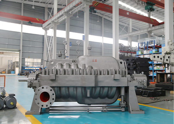
- Commodity name: API-BB3 Series MDK Horizontal Split-case Multistage Centrifugal Pump
Flow Range: 20~2500 m³/h<br> Head Range: 60~ 1200m<br> Operating Temperature: -40~200 ℃<br> Design Pressure: 16 MPa<br> Design Speed: 2980 rpm / 1480 rpm<br> Transported Media: Clean water, oil products, chemical solvents, wastewater and other liquids with solid content ≤ 3% (subject to material selection)<br><br><br>
Product Description
The API-BB3 Series MDK Horizontal Split-case Multistage Centrifugal Pump is independently developed by our company to meet the production demands and equipment upgrading needs of mining, petroleum, chemical, power, steel and other industries. Drawing on advanced international technologies and combining the characteristics of the domestic market as well as our decades of experience in design and manufacturing, this product line has been launched for 20 years. Through continuous exploration and innovation over the years, its hydraulic design, manufacturing quality and monitoring & control performance have reached an excellent level.
Product Features
1. This BB3 series MDK horizontal split-case multistage centrifugal pump adopts an integral structure with axial split design, double-end support and automatic axial force balance. The pump casing is horizontally split along the shaft centerline. The upper cover can be opened quickly for inspection and maintenance without dismantling pipelines or motors, greatly improving operation and maintenance efficiency. The double-end bearing support ensures high rigidity of the shaft system for stable operation with negligible vibration. The series impellers are arranged back-to-back to realize automatic balance of axial force, and the residual axial force is borne efficiently by the thrust bearing. This design reduces component wear and extends service life. Meanwhile, the split-case structure features flexible installation and reliable operation, suitable for a wide range of industrial applications.
2. Designed in strict accordance with the international API 610 standard, the pump fully complies with the structural requirements for API 610 BB3 type pumps. The whole process including hydraulic model optimization, component strength verification and sealing performance test follows stringent standards from design and material selection to manufacturing. It delivers outstanding reliability and adaptability under harsh working conditions such as high temperature, high pressure and long-term continuous operation, well meeting the high-end requirements of petroleum, chemical, power and other industries.
3. The pump is equipped with heavy-duty center support, with supporting points precisely aligned with the pump centerline. It ensures uniform stress distribution during operation, effectively counteracting radial force and vibration generated by fluid delivery and preventing casing deformation and leakage caused by uneven force. The robust support structure also enhances impact resistance, enabling stable long-term operation under severe working conditions in mining, metallurgy and other sectors.
4. Featuring compact and well-organized overall structure with rationally arranged components, the pump maximizes performance within limited installation space and is easy to install even in narrow areas. The optimized structure lowers friction between parts, reduces operating noise and improves running stability. All key components undergo strict quality inspection and performance testing, and selected materials are well adapted to industrial working conditions. This significantly boosts operational reliability, cuts downtime and reduces overall maintenance costs.
5. The pump boasts excellent corrosion and wear resistance. Key wetted parts such as pump casing and impellers can be manufactured from carbon steel, stainless steel, duplex steel and other wear & corrosion resistant alloys according to different transported media. With special surface treatment, the pump can effectively resist erosion and abrasion caused by acid, alkali, salt spray and impurity-containing fluids. It is applicable for conveying various complex media including clean water, oil products, chemical solvents and wastewater, extending equipment service life and lowering the replacement frequency of wearing parts.
Application
1. Power Industry: Boiler feed water pump, circulating water pump and condensate pump for thermal power plants.
2. Petroleum & Chemical Industry: Water injection for oilfields, pipeline oil transportation, and service for refineries and chemical plants.
3. Mining & Metallurgy: Mine drainage and high-pressure water supply for mineral processing plants.
4. Water Conservancy & Municipal Engineering: Long-distance water transmission, urban high-pressure water supply, flood control and drainage.
5. General Industrial Processes: High-pressure fluid delivery for steel, papermaking, pharmaceutical and other industries.
Selection Guidelines
1. Determine pump model and stage quantity according to flow rate, head, medium, operating temperature and pressure.
2. Select alloy materials (carbon steel, stainless steel, duplex steel) for high-temperature or corrosive working conditions.
3. A first-stage double-suction impeller is recommended to improve anti-cavitation performance.
4. Adopt API 610 standard pumps for critical working conditions.
Order Notice
Hunan Sanchang Pump Industry Co., Ltd. provides customized production service for API-BB3 series MDK horizontal split-case multistage centrifugal pumps. Feel free to contact us for inquiries.
-
Flow Range: 20~2500 m³/h
Head Range: 60~ 1200m
Operating Temperature: -40~200 ℃
Design Pressure: 16 MPa
Design Speed: 2980 rpm / 1480 rpm
Transported Media: Clean water, oil products, chemical solvents, wastewater and other liquids with solid content ≤ 3% (subject to material selection)
-
API-BB3 Series MDK Horizontal Split-case Multistage Centrifugal Pump Outline Drawing

-
Installation Procedures
1. Foundation Construction & Inspection
Cast a solid concrete foundation according to the pump dimensions and weight. The length, width and height of the foundation shall comply with design requirements, and be capable of bearing the maximum load and vibration generated during pump operation.
Check the flatness of the foundation surface. The horizontal deviation shall be within 0.05 - 0.1 mm per meter. Ensure the foundation is free from cracks, honeycombs, pitting and other defects. Meanwhile, reserve anchor bolt holes with position and dimensions precisely matching the pump anchor bolts.
2. Pump Positioning & Preliminary Alignment
Use suitable lifting equipment to place the pump steadily onto the foundation, and align the pump anchor bolts with the reserved holes. Place shims under the pump base to preliminarily adjust the level and elevation. Measure the levelness via the pump suction/discharge flanges or machined surfaces of the pump casing to keep it within allowable range.
Install anchor bolts and fasten nuts loosely. Do not fully tighten them to reserve space for precise alignment and secondary grouting.
3. Piping Connection
Before pipe installation, thoroughly clean the flange faces of the pump and pipelines to remove burrs, oil stains and debris, ensuring smooth and flat sealing surfaces.
Install gaskets and select proper gasket materials such as oil-resistant rubber and PTFE based on the properties of conveyed media. Connect pipelines to pump flanges and tighten bolts evenly in compliance with specified torque. Uneven force shall be avoided to prevent flange deformation and poor sealing.
Ensure no external forced stress is applied to the pump during connection. The weight and stress of pipelines shall not be transmitted to the pump body. Adjust pipe supports and hangers as required, and adopt cold drawing or thermal compensation for pipelines when necessary.
4. Motor Installation & Shaft Alignment
For split-coupled pump and motor units, keep the motor shaft and pump shaft concentric within specified tolerance. When connected via a coupling, the radial runout deviation between two shafts shall not exceed 0.05 - 0.1 mm, and the axial deviation shall not exceed 0.05 - 0.15 mm.
Use dial indicators for accurate measurement and alignment by adjusting the motor position and shim thickness. After alignment, fully tighten the motor anchor bolts and recheck the alignment to confirm no displacement occurs during fastening.
5. Lubrication & Cooling System Installation
For pumps equipped with lubrication and cooling systems, install the lube oil piping and cooling water pipelines correctly. Keep the lubrication piping clean and well sealed to prevent foreign matter from entering the lubrication system.
Make sure cooling water flows in the correct direction, with water flow rate and pressure meeting operational requirements. Install necessary valves and gauges on cooling pipelines for regulation and condition monitoring.
6. Electrical Connection & Grounding
Connect power cables and control cables in accordance with the rated voltage, power and other parameters of the pump and motor. Ensure cables comply with specifications, with firm connection and good insulation.
Install the grounding wire for the motor. The grounding resistance shall be no more than 4 Ω to guarantee equipment and personal safety. Use dedicated grounding cables with reliable connection to prevent looseness and poor contact.
7. Post-installation Inspection & Cleaning
Conduct a comprehensive inspection: verify all anchor bolts and connecting bolts are fully tightened, pipelines are securely connected, sealing performance is intact, and lubrication & cooling systems work properly.
Clear away sundries and tools around the pump to keep the site tidy. Rotate the pump rotor manually to check flexible rotation, and confirm no jamming or abnormal noise exists.
Operation Procedures
1. Pre-start Preparation
Recheck all connecting parts for looseness and sealing surfaces for leakage.
Inspect the lubricant level and quality. The oil level shall stay within the marked range, and the oil shall be clean without impurities or emulsification. Replace the lubricant immediately if it fails to meet requirements.
Open the pump suction valve to fill the pump with conveyed medium, and vent internal air via the air vent valve until no air escapes.
Verify the motor rotation direction by inching the motor. Adjust the phase sequence if the rotation is incorrect to ensure the impeller runs in the right direction.
Check the normal operation of gauges including pressure gauges, thermometers and flow meters to ensure accurate readings for operational monitoring.
2. Pump Start-up
Start the motor and gradually raise the speed to the rated value. During start-up, closely monitor operating conditions including noise, vibration, current and pressure.
After the pump reaches rated speed, check whether discharge pressure and flow rate meet standard values. Shut down the pump immediately if any abnormality occurs, troubleshoot the faults before restarting.
3. In-operation Maintenance & Monitoring
Regularly monitor operating parameters such as suction/discharge pressure, flow rate, motor current, temperature and vibration, and keep detailed records. Perform inspection every 1 to 2 hours for timely fault detection.
Listen for abnormal noise and vibration from the pump and motor. Stop operation for maintenance if abnormalities are found, which may be caused by unbalanced impellers, damaged bearings, pipeline resonance and other issues.
Check sealing leakage. Minor leakage is acceptable as long as it is within the permitted range. Replace sealing components or conduct repairs in time if excessive leakage occurs.
Monitor the temperature and level of lubricant. The oil temperature shall be maintained between 40 ℃ and 60 ℃. Check the cooling system and other potential faults if the oil temperature is too high. Top up lubricant regularly to keep the oil level normal.
Confirm the properties and temperature of conveyed media comply with operating requirements. Avoid performance degradation and service life reduction caused by corrosive media, viscosity change or extreme temperature.
4. Shutdown Procedures
Gradually close the discharge valve to minimize flow rate, then stop the motor. This operation prevents water hammer that may damage the pump and pipelines.
Close the suction valve. Drain the medium inside the pump as needed. Complete drainage is recommended if the medium is corrosive or prone to crystallization.
For long-term shutdown, perform maintenance work: clean the pump casing, apply anti-rust oil, inspect and replace wearing parts, so as to prevent component rust and damage and extend service life.
-
1. Pump fails to start or runs at low speed
Causes
Power supply faults: power outage, blown fuse, poor cable connection, etc.
Motor faults: winding short circuit, open circuit, motor shutdown due to overload protection.
Foreign objects inside the pump jam the impeller.
Misaligned coupling causing misalignment between motor shaft and pump shaft and excessive resistance.
Insufficient starting torque caused by low voltage or improperly selected motor.
Solutions
Inspect power supply, restore power, replace fuses and repair cable connections.
Repair or replace the motor; identify and eliminate overload causes.
Dismantle the pump casing and remove foreign objects.
Realign the coupling to ensure concentricity of motor shaft and pump shaft.
Check power voltage to keep it within the rated range, or select a proper motor.
2. Insufficient flow rate
Causes
Blocked suction pipeline or partially closed valve restricting medium intake.
Severely worn impeller leading to excessive clearance between impeller and pump casing and medium backflow.
Worn wear ring causing increased internal leakage and reduced flow.
Pump speed below rated value due to motor or transmission faults.
Increased medium viscosity resulting in higher flow resistance.
Solutions
Clean the suction pipeline and fully open the valve.
Replace the worn impeller.
Replace the wear ring.
Inspect the motor and transmission to restore rated speed.
Select a suitable pump model or pre-treat the medium to reduce viscosity according to medium properties.
3. Insufficient head
Causes
Damaged or reversely installed impeller reduces hydraulic work output.
Entrapped air inside pump causes air binding and impedes liquid transportation.
Excessive discharge line resistance from overlength piping, excessive elbows or throttled discharge valve.
Sub-rated rotating speed lowers hydraulic head generated by impeller.
Solutions
Repair or replace the impeller and ensure correct installation.
Re-vent the pump to remove all internal air.
Optimize discharge pipeline layout to reduce unnecessary resistance and fully open valves.
Inspect the motor and transmission system to restore rated speed.
4. Pump fails to start or runs at low speed
Causes
Power supply faults: power outage, blown fuse, poor cable connection, etc.
Motor faults: winding short circuit, open circuit, motor shutdown due to overload protection.
Foreign objects inside the pump jam the impeller.
Misaligned coupling causing misalignment between motor shaft and pump shaft and excessive resistance.
Insufficient starting torque caused by low voltage or improperly selected motor.
Solutions
Inspect power supply, restore power, replace fuses and repair cable connections.
Repair or replace the motor; identify and eliminate overload causes.
Dismantle the pump casing and remove foreign objects.
Realign the coupling to ensure concentricity of motor shaft and pump shaft.
Check power voltage to keep it within the rated range, or select a proper motor.
5. Excessive vibration or abnormal noise
Causes
Misalignment between pump shaft and motor shaft.
Unbalanced impeller caused by uneven wear or attached foreign matter.
Damaged bearings leading to shaft runout and vibration.
Unstable foundation or loose anchor bolts causing pump shaking during operation.
Pipeline resonance resulting from poorly fixed or improperly arranged pipes.
Solutions
Realign the coupling to ensure shaft concentricity.
Conduct dynamic balance test on the impeller, remove foreign matter or replace the impeller.
Replace damaged bearings.
Reinforce the foundation and tighten anchor bolts.
Re-fix pipelines and optimize layout to eliminate resonance.
6. Leakage at shaft seal
Causes
Damaged mechanical seal, such as worn seal faces or aged sealing rings.
Worn shaft sleeve leading to enlarged clearance between seal face and sleeve.
Insufficient or interrupted seal flush fluid supply.
Excessive shaft axial play affecting stable operation of the mechanical seal.
Solutions
Replace the mechanical seal assembly.
Replace the worn shaft sleeve.
Inspect the seal flush system and ensure normal fluid supply.
Check and adjust shaft axial play to the specified range.
7. Overheated motor
Causes
Motor overload caused by excessive flow, excessive head or medium viscosity beyond design range.
Poor heat dissipation due to excessive dust or blocked ventilation openings on the motor.
Abnormally high or low power voltage.
Motor winding short circuit or ground fault leading to increased current.
Solutions
Adjust pump operating conditions to match design parameters, or replace with a suitable motor.
Clean dust on the motor and clear ventilation openings to improve heat dissipation.
Stabilize power voltage within the rated range.
Repair winding short circuit or ground fault; replace the motor if necessary.
Customer Case
Product Consulting
If you are interested in our products, please leave your email, we will contact you as soon as possible, thank you!


Hunan Sanchang Pump Co., Ltd.
| Email: | info@sanchangpump.net |
| Hotline: | +86 181 4266 2779 |
| +86 193 1300 1794 | |
| Mobile/Wechat/WhatsApp: | +86 181 4266 2779 |
| Address: | No.517,Xiangfu Road, Yuhua |
| District, Changsha City | |
| Hunan Province, P.R.C |
