Recommend Products
Contact Us
| Email: | sales@sanchangpump.com |
| Hotline: | +86 133 0748 1676 |
| +86 193 1300 1794 | |
| Mobile: | +86 133 0748 1676 |
| Wechat: | +86 193 1300 1794 |
| Address: | No.517,Xiangfu Road |
| Yuhua District, | |
| Changsha City | |
| Hunan Province, P.R.C |


D-typeHorizontal Multistage Centrifugal Pump
Classification:
BB4 Multistage Centrifugal Pump
Mining industry
D-type horizontal multistage centrifugal pump
Multi-stage pump for mine
Key words:
water pump
Head range: 50~2000m
Conveying temperature: 0 ℃ ~ 80 ℃
Inlet pressure: allowable inlet pressure 0.6MPa
Sealing form: packing seal, mechanical seal
Water pump material: HT200, HT250, QT600, ZG, 304, 316, 316L, 317L, 904L, CD4-MCu, etc

Hotline:
- Product Description
- Performance Parameter
- Installation Drawings
- Installation And Use
- Faults And Solutions
-
- Commodity name: D-typeHorizontal Multistage Centrifugal Pump
Flow range: 3.75~1400 m3/h<br>Head range: 50~2000m<br>Conveying temperature: 0 ℃ ~ 80 ℃<br>Inlet pressure: allowable inlet pressure 0.6MPa<br>Sealing form: packing seal, mechanical seal<br>Water pump material: HT200, HT250, QT600, ZG, 304, 316, 316L, 317L, 904L, CD4-MCu, etc</br></br></br></br></br>
Hunan Sanchang Pump Industry Co., Ltd. specializes in producing ZD type high-efficiency and energy-saving self-balancing multistage pumps, D type series multistage pumps, S type series double suction pumps, DG type series boiler feed pumps, R type high temperature hot water pumps, IH series chemical pumps and a series of clean water pumps, welcome Customers come to consult!
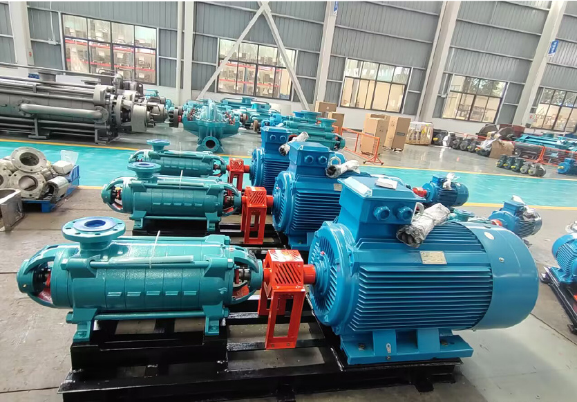
D-type horizontal multistage centrifugal pump is a multistage segmental centrifugal pump, which is suitable for water supply and drainage in mines, factories and cities. It is used to transport clear water without solid particles or liquids with physical and chemical properties similar to clear water. The temperature of the medium to be transported is 0 ℃ ~ 80 ℃, and the allowable inlet pressure is 0.6MPa.

Structure type:
D-type horizontal multistage centrifugal pump for horizontal installation, in addition to the D16-60-type pump suction direction vertical upward, the rest of the pump suction direction is horizontal, all D-type multistage pump discharge direction vertical upward, the axial force by the balance plate to balance, the shaft seal is generally used packing seal, according to user needs can also be used mechanical seal. In addition to D85-67,D155-67 type pump using sliding bearings, thin oil lubrication, the rest of the use of rolling bearings, grease lubrication.
Model description:
D280-43 × 5;
D-segmental multistage centrifugal clean water pump;
280-indicates the flow rate of the pump (m3/h);
43-indicates the single-stage head of the pump (m);
5-indicates series.
Direction of rotation:
Clockwise rotation as viewed from the motor end to the pump.
Material of main parts:
Pump flow parts are made of cast iron, the material of the shaft is 45 steel.
Scope of package:
The pump is supplied with motor and base, and can be equipped with functional base or its own base. The manufacturer also provides accessories (including discharge cone pipe, gate valve, bottom valve and check valve) and spare parts (including impeller, sealing ring, guide vane sleeve, balance plate and shaft sleeve).
Structure description:
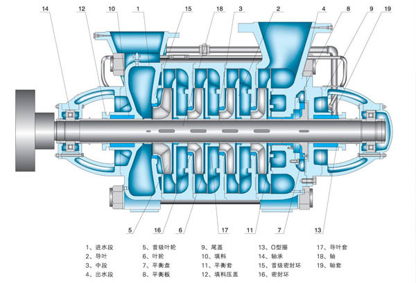
D, DG, MD, DF, DY pumps are mainly composed of fixed parts, rotor parts, bearings and shaft seals.
1. Partial stator
It is mainly composed of water inlet section, middle section, water outlet section and guide vane, etc., and each section is tightened with a bar to form a working room. The inlet of D-type multistage pump is horizontal and the outlet is vertical upward. DG pump inlet and outlet are both vertically upward. MD, DF and DY pumps have their outlets vertically upward and their inlets are generally horizontal. As required, they can also be produced in the vertical upward direction.
2. Rotor part
It is mainly composed of shaft, impeller, balance plate and shaft sleeve. The shaft transmits power to the impeller to make it work; the balance disc is used to balance the axial force; the shaft is equipped with a replaceable sleeve to protect the shaft.
3. Bearing part
It is mainly composed of bearing body, bearing and bearing gland. In addition to 85-67, 155-67, 600-60 type pump using sliding bearings, thin oil lubrication, the rest of the pump are used rolling bearings, grease lubrication. 85-67, 155-67 can also use rolling bearing structure.
4. Shaft seal
Generally, soft packing is used for sealing, which is mainly composed of sealing body, packing and water retaining ring on water inlet section and tail cover. There is a constant pressure of water in the sealing cavity, which plays the role of water seal, water cooling and lubrication. D type pump water seal generally comes from the high pressure water in the pump, DG, MD, DF, DY type pump comes from the pressure water in the pump or external water supply. DG, MD, DF, DY type pump more mechanical seal.
5. Transmission
The pump is directly driven by the prime mover through an elastic coupling. From the prime mover end, the pump rotates clockwise.
-
Parameter range:
Flow range: 3.75~1100 m3/h
Lug range: 50~1800m
Conveying temperature: 0 ℃ ~ 80 ℃
Inlet pressure: allowable inlet pressure 0.6MPa
Sealing form: packing seal, mechanical seal
Water pump material: HT200, HT250, QT600, ZG, 304, 316, 316L, 317L, 904L, CD4-MCu, etc
-

-
(I) assembly sequence:
1) Install the seal ring tightly on the inlet section and the guide vane baffle respectively.
2) suit the guide wing on the middle section, and then install the guide wing baffle on all the middle sections.
3) Pass the shafts of the installed shaft sleeves A and B through the water inlet section and push them into the impeller, spread a layer of paper pad on the middle section, install the middle section, push them into the second impeller, repeat the above steps, and finish loading all the impellers and the middle section.
4) Install the balance ring, balance sleeve and water outlet guide wing on the water outlet section respectively.
5) Install the water outlet section on the middle section, and then fasten the water inlet section, the middle section and the water outlet section together with tension bolts.
6) Assemble the flat punching plate and shaft sleeve B (50DB pump does not have this piece).
7) Install the paper pad on the tail cover, install the tail cover on the water outlet section, and install the packing, packing ring and packing gland into the filling chamber of the water inlet section and the tail cover in sequence.
8) Install the bearing body above the water inlet section and the tail cover respectively, and fasten it with bolts.
9) Install the bearing positioning sleeve and ball bearing, and fix it with nut.
10) Put an appropriate amount of butter into the bearing body, and put the paper pad on the bearing cover, and install the bearing cover on the bearing body and fasten it with screws.
11) Install the coupling components and bleed the cock and all square plugs.
Do the removal steps that are not opposite.
(II) installation:
1. Preparation before installation.
1) Check the water pump and motor.
2) Prepare tools and lifting machinery.
3) Check the basis of the machine.
2. Installation sequence:
1) The whole set of water pump is transported to the site. The person with the base has installed the motor. It is not necessary to remove the water pump and motor when leveling the base.
2) Place the base on the foundation, pad wedge-shaped shim iron near the anchor screw, pad the base about 20~40mm high, and prepare to fill the water screw slurry after leveling.
3) Check the levelness of the base with a level, and after leveling, tighten the anchor nut and fill the base with cement slurry.
4) After 3~4 days of cement drying, check the levelness again.
5) Wash and remove the dirt on the support plane of the base, the water pump foot and the motor foot;, and put the water pump and motor on the base.
6) Adjust the level of the pump shaft, tighten the nut properly after leveling to prevent walking, install the motor after adjustment is completed, pad the iron plate at the non-horizontal place, and leave a certain gap between the pump and the coupling.
7) Put the flat ruler on the coupling, check whether the axis line of the water pump coincides with the axis line of the motor. If it is not heavy, pad the motor or the foot of the pump with a thin sheet to level the outer circle of the two couplings with the flat ruler. Then take out several thin iron sheets of the pad, replace the iron sheets with the whole iron sheets that have been planed, and recheck the installation.
In order to check the installation accuracy, use feeler gauges at several opposite positions to measure the clearance between the two coupling planes. The difference between the maximum and minimum clearance on a circle of the coupling plane shall not exceed 0.3mm, and the difference between the upper and lower or left and right center lines at both ends shall not exceed 0.1mm.
(III) start and stop:
1) Clean the oil on the shaft and other oiled parts.
2) Clean the bearing and oil chamber with gasoline, and wipe it with cotton yarn.
3) Add calcium-based spring oil in the bearing body.
4) If the test is successful, check whether the motor is turning correctly, prevent the water pump from turning to loosen the nut, and then start the motor.
5) Inject water into the pump or drain water from the empty pump.
6) Close the valve on the discharge pipe and the pressure gauge cock.
7) After the above process is completed, start the motor and open the pressure gauge cock.
8) When the water pump is running at normal revolutions, the pressure gauge shows the appropriate pressure. Then open the vacuum gauge and gradually open the gate valve on the drain line to the required pressure.
9) When stopping the pump, slowly close the gate valve on the drain pipe, close the vacuum gauge cock, stop the motor, and then close the pressure gauge cock.
10) When the water pump is stopped for a long time, the water pump should be disassembled, the water of the pump parts should be wiped off, and the sliding surface should be coated with anti-rust oil and stored properly.
-
1) Pay attention to the bearing temperature of the water pump, which should not exceed the outside temperature of 35 degrees but should not exceed 75 degrees.
2) The normal water leakage degree in the packing room is not more than 15 ml per minute, and the compaction degree of the packing gland should be adjusted at any time.
3) Check the coupling regularly and pay attention to the temperature rise of the motor bearing.
4) During operation, if noise or abnormal sound occurs, stop immediately to check the cause.
Previous Page
Next Page
Product Consulting
If you are interested in our products, please leave your email, we will contact you as soon as possible, thank you!


