

MDP wear-resistant self-balancing multistage pump for mine
Classification:
Mining industry
Water conservancy industry
Electric power industry
Self-balancing multistage centrifugal pump
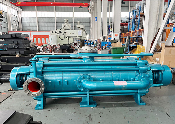
MDP wear-resistant self-balancing multistage pump for mine
Multi-stage pump for mine
MDP wear-resistant self-balancing multistage pump for mine
Key words:
water pump
Head range: 50~2000m
Conveying temperature: 0 ℃ ~ 80 ℃
Inlet pressure: allowable inlet pressure 0.6MPa
Sealing form: packing seal, mechanical seal
Water pump material: HT200, HT250, QT600, ZG, 304, 316, 316L, 317L, 904L, CD4-MCu, etc

Hotline:
- Product Description
- Performance Parameter
- Installation Drawings
- Installation And Use
- Faults And Solutions
-
- Commodity name: MDP wear-resistant self-balancing multistage pump for mine
Flow range: 3.75~1400 m3/h<br>Head range: 50~2000m<br>Conveying temperature: 0 ℃ ~ 80 ℃<br>Inlet pressure: allowable inlet pressure 0.6MPa<br>Sealing form: packing seal, mechanical seal<br>Water pump material: HT200, HT250, QT600, ZG, 304, 316, 316L, 317L, 904L, CD4-MCu, etc</br></br></br></br></br>
MDP type self-balancing horizontal multi-stage pump is a high-efficiency high-pressure multi-stage centrifugal pump product researched and developed according to API610 standard by adopting advanced technology of similar foreign products combined with many years of design experience of the company, using hydraulic model of high-efficiency and energy-saving products recommend by the state. It has the advantages of wide high efficiency area, wide performance range, good cavitation performance, few wearing parts, convenient installation and maintenance, etc. The reliability is greatly improved, the trouble-free running time is more than 3 times that of ordinary pumps, and the maintenance cost of users is greatly reduced, thereby reducing the life cycle cost of the pump. The high-pressure self-balancing segmental centrifugal pump innovates the structural form of the traditional multistage centrifugal pump, cancels the axial force balance mechanism of the multistage centrifugal pump, and is a substitute for the D and DG multistage centrifugal pump with the balance disc or balance drum structure. Because there is no balance device, that is, there is no balance disc friction loss and no balance return loss, the pump efficiency is 5-14 higher than that of multi-stage pumps of the same category. At the same time, the wear of the balance disc and the balance disc seat caused by the failure of the balance device or Various faults such as rotor seizure greatly extend the service life of the pump. Years of operation has proved that the performance of the product has reached the advanced level of similar products in the world.

Model meaning:
Play.com: D(DF 、 dy 、 MD 、 DS) 450 - 95 × 12 (P)
DP stands for self-balancing horizontal multistage water centrifugal pump
DPF said self-balancing corrosion-resistant horizontal multistage centrifugal pump
DYP means self-balancing horizontal multistage centrifugal oil pump
MDP said self-balancing wear-resistant horizontal multistage centrifugal pump for mining
DS indicates self-balancing first-stage double-suction centrifugal pump (effectively improving cavitation allowance)
450 means the design point flow is 450 m3/h
95 means that the single-stage head at the design point is 95m.
12 indicates that the number of stages is 12
Working principle:
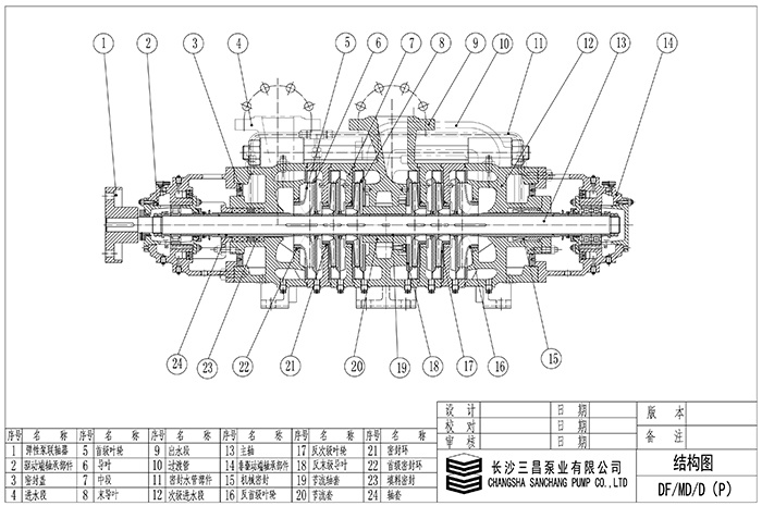
Driven by the motor, the shaft rotates to work on the liquid to increase its energy, so that the required amount of liquid is continuously sent out from the suction tank through the vertical water outlet of the water inlet section, positive impeller, positive guide vane, middle section and water outlet section of the pump, transition pipe, secondary water inlet section, reverse impeller, anti-guide vane and water outlet section.
Structural features:
MDP self-balancing multistage pump is a horizontal segmental multistage centrifugal pump with single suction or double suction inlet. The suction inlet of the pump can be vertically upward or horizontally, and the discharge outlet can be arranged vertically upward. Mainly include: water inlet section, middle section, water outlet section, secondary water inlet section, positive guide vane, reverse guide vane, positive impeller, reverse impeller, shaft, throttling, decompression device, stop sleeve, bearing body, transition pipe and other parts. The middle section is connected with high-strength bar bolt and water inlet and outlet sections. The sealing surfaces between the water inlet section, middle section and outlet section of the pump are hard sealed with molybdenum disulfide grease metal surface; the rotor is composed of positive impeller, throttling and decompression device, reverse impeller, shaft sleeve and other parts installed on the shaft. The bearing adopts "solid-swimming" dry oil lubrication structure. The driving end adopts cylindrical roller bearing and the end adopts angular contact ball bearing. The working room of the pump is composed of water inlet section, middle section, water outlet section, secondary water inlet section, positive guide vane, anti-guide vane and transition pipe.
The rotor part and the fixed part are equipped with a sealing ring, guide vane sleeve, etc. for sealing. When the wear degree of the sealing ring and guide vane sleeve has affected the working performance of the pump, it should be replaced in time.
The sealing form of the shaft has two kinds of mechanical seal and packing seal. When the pump uses packing seal, the position of the packing ring should be placed correctly, and the tightness of the packing must be appropriate, so that the liquid can leak out one drop by one. Various sealing components of the pump are installed in the sealing cavity, and water with a certain pressure is introduced into the cavity to play the role of water seal, water cooling and water lubrication. A replaceable shaft sleeve is installed at the shaft seal to protect the pump shaft; the self-balancing multistage pump can replace the bearing and seal without disassembling the inlet and outlet. This series of pumps are directly driven by the prime mover through an elastic pin coupling or a diaphragm coupling. From the prime mover direction, the pump is clockwise rotation.

Conveying range
It can be used to transport clear water with particle content ≤ 1.5, particle ≤ 1.3mm, temperature ≤ 105 ℃ or other liquids with physical and chemical properties similar to clear water. It can also be used to transport hot water, oil, corrosive or abrasive media at temperatures ≤ 225 ℃ by changing the material (and structure) of the pump, sealing form and increasing the cooling system. Materials are HT200, QT600, ZG, 304, 304L, 316L, 317L, 904L, CD4 and other materials for users to choose from.
Model Description
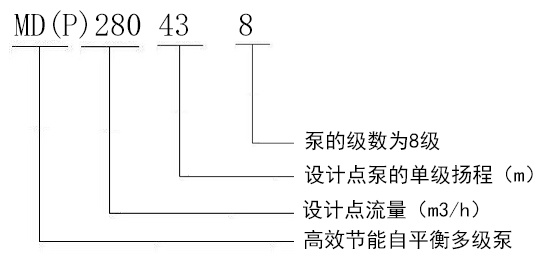
Example: MD280J-43X8(P)
MD(P)-energy-efficient self-balancing high wear-resistant multistage pump
280-Flow at design point (m3/h)
J-Mechanical seal (not marked as packing seal)
43-Single stage head of pump at design point (m)
8-The number of stages of the pump is 8

-
Flow range: 3.75~1400 m3/h
Head range: 50~2000m
Conveying temperature: 0 ℃ ~ 80 ℃
Inlet pressure: allowable inlet pressure 0.6MPa
Sealing form: packing seal, mechanical seal
Water pump material: HT200, HT250, QT600, ZG, 304, 316, 316L, 317L, 904L, CD4-MCu, etc
-

-
Preparation before 1. installation
1. Determine the installation location of the multi-stage pump: the location where the installation is stable and easy to operate, repair and overhaul should be selected.
2. Confirm the location of the water injection port: the water injection port should be set at the inlet pressure pipe and about 20cm away from the pump to avoid backflow and change the impeller speed of the multi-stage pump.
3. Deal with the inlet pressure pipeline: prepare the pipeline and flange connection part to ensure that the connection part is free of foreign matter or rust.
4. Prepare the power supply and cables: select the appropriate cable according to the power requirements of the multi-stage pump, and ensure that the cable quality is good.
2. installation steps
1. Assemble the components: Assemble the components according to the requirements of the instructions or drawings, and determine the positions of the drain, vent, and lubrication parts.
2. Install the multi-stage pump: place the multi-stage pump in the installation position, pay attention to the smooth contact between the base of the multi-stage pump and the ground, and the seat surface of the base is perpendicular to the ground.
3. Interface connection: connect the inlet pressure pipe and the outlet pressure pipe. The connecting flange shall be parallel and horizontal without distortion and deformation.
4. cable wiring: according to the multi-stage pump electrical connection diagram wiring, pay attention to the standardization of wiring and reasonable wiring.
5. Water injection and drainage: open the stop valve of the inlet pressure pipe of the multi-stage pump, and introduce clean water (or including the added pump irrigation and drainage liquid) into the pump to avoid abnormal noise caused by pump vibration.
6. Adjust the pump: adjust the frequency converter or on-demand reducer to ensure that the motor of the multi-stage pump works normally and the water flow speed is moderate.
Inspection after 3. installation
1. Check the overall installation of the pump: to ensure that the base of the multi-stage pump is stable and vertical.
2. Check the connection of each pipeline: confirm whether each interface is tightly connected and whether there are abnormal conditions such as abnormal noise.
3. Pump movement test: turn on the power, check whether the motor rotation is stable, whether the sound is normal, whether the pump is leaking, etc.
4. System pressure test: In the experiment, the intelligent instrument records data such as the opening and closing state of the control valve and the water flow. During the test, pay attention to whether there are abnormal conditions such as noise, vibration or high temperature around the system, and deal with any abnormalities in time.
5. Check the wires: Confirm whether the wires are correctly wired and free of damage and other relevant details meet the installation specifications.
The above is a detailed explanation of the installation steps of the multi-stage pump. I hope readers can install the multi-stage pump correctly according to the above steps to ensure that the installed multi-stage pump can operate normally and provide better protection for production and life.
-
Fault one: multi-stage pump does not absorb water pressure gauge and vacuum gauge pointer beating violently
Cause: 1. Insufficient water injection and diversion 2. Air leakage at the connection between pipeline and instrument 3. Excessive suction
Solution: 1. Check whether the bottom valve leaks. 3. Lower the suction height
Fault two: multi-stage pump does not absorb water vacuum table indicates a high degree of vacuum
Reason: 1. The bottom valve is not opened or blocked 2. The resistance of the suction pipeline is too large 3. The filter is blocked
Solution: 1. Check the bottom valve 2. Replace the water absorption 3. Clean the filter
Fault three: pressure gauge pressure but still not out of water
Reason: 1. The resistance of the outlet pipe is too large 2. The rotation direction is wrong 3. The outlet pipe valve is not open 4. The impeller is blocked
Solution: 1. Check or short water pipe 2. Check the motor. Two-phase intermodulation 3. Open the outlet valve 4. Remove the dirt in the impeller
Fault four: can not reach the design flow
Reason: 1. air inhalation 2. due to the lowering of the water level. The submerged depth is not enough. 3. The impeller is blocked by foreign matter. 4. The rotor is severely worn.
Solution: 1. Check the air leakage site and exclude 2. Extend the suction pipe. Deepen the flooding depth 3. Remove and remove foreign objects 4. Replace the sealing ring
Fault five: multi-stage pump power consumption is too large
Reason: 1. Packing is too tight. And heat 2. The flow is too large 3. The rotating body and the shell rub 4. The pump bearing is worn 5. The pump shaft is bent.
Solution: 1. Relax the packing pressure appropriately 2. Close the gate valve opening 3. Trim the position of the rotary body and the shell 4. Replace the bearing 5. Replace or correct
Fault six: multi-stage pump vibration increased
Reason: 1. The impeller is partially blocked 2. The impeller is damaged 3. The flow rate is too small 4. The pump shaft is not concentric with the motor 5. The bearing is damaged 6. Air is mixed. Cavitation occurs
Solution: 1. Disassemble and remove foreign matter 2. Replace the impeller 3. Slightly open the outlet valve 4. Point aligning 5. Change the suction position. Improved water absorption
Previous Page
Product Consulting
If you are interested in our products, please leave your email, we will contact you as soon as possible, thank you!


