
Products
Recommend Products
Contact Us
| Email: | info@sanchangpump.net |
| Hotline: | +86 181 4266 2779 |
| +86 193 1300 1794 | |
|
Wechat: |
+86 181 4266 2779 |
|
WhatsApp: |
+86 181 4266 2779 |
| Address: | No.517,Xiangfu Road |
| Yuhua District, | |
| Changsha City | |
| Hunan Province, P.R.C |

API 610 OH2 Horizontal Single-Stage Centrifugal Pump
Classification:
API 610 Pump
Power Plant
Metallurgical
Key words:
Process Pump
Petrochemical Pump
OH2 Pump


Hotline:
- Product Description
- Performance Parameters
- Installation Drawings
- Installation and Operation
- Faults and Solutions
-
- Commodity name: API 610 OH2 Horizontal Single-Stage Centrifugal Pump
Flow Range: 5.5~2600 m3/h</br> Head Range: 16~250 m</br> Fluid Temperature: -80~450 ℃</br> Inlet Pressure: 0~7.5 MPa</br> Shaft Seal: mechanical seal</br> Available Materials: HT200, HT250, QT600, ZG, 304, 316, 316L, 317L, 904L, CD4-MCu, etc</br></br></br></br>
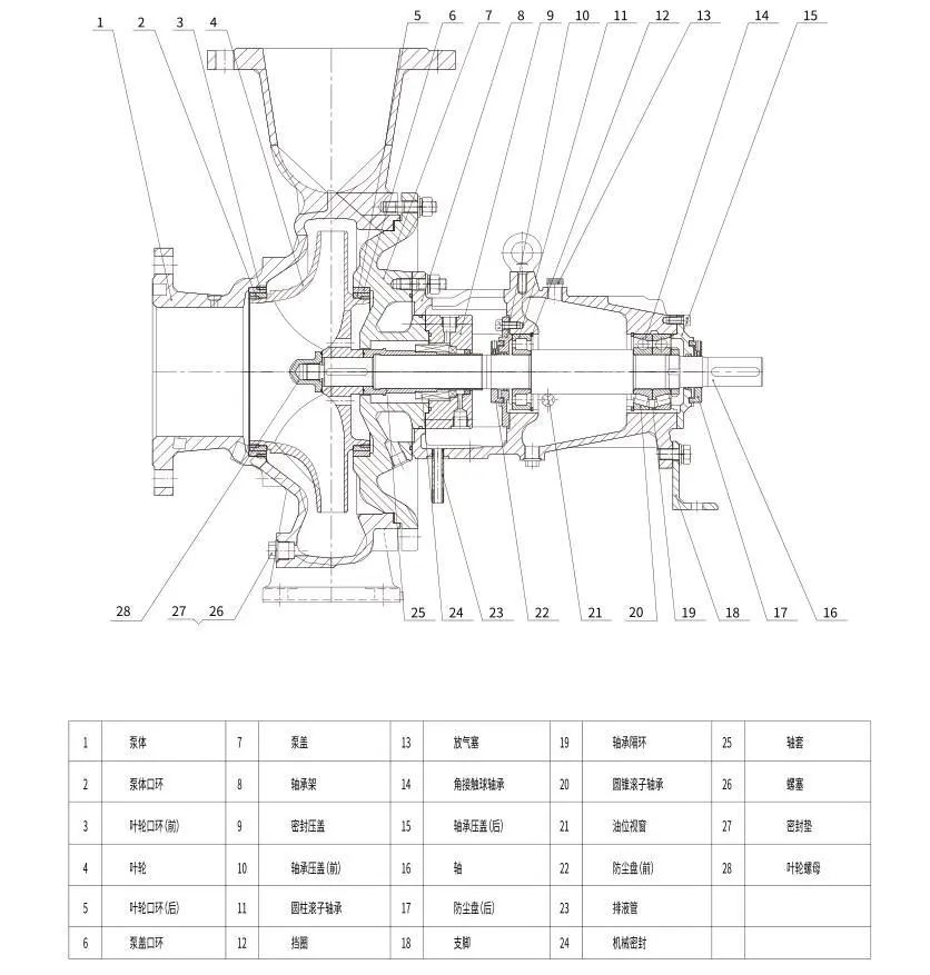
OH2 pump is a horizontal single-stage overhung centrifugal pump fully compliant with API 610 12th edition (ISO 13709). It features an overhung impeller structure with a single suction design, horizontal foot-mounted pump casing, and separate bearing housing arranged on the rear side of the impeller. This type pump is the mainstream process pump for heavy-duty petroleum, chemical and power industries, engineered for continuous stable operation under severe temperature, pressure and corrosive medium working conditions. It adopts modular design for easy interchange of spare parts and standardized maintenance procedures.

Model Description
Example: COZ (III) 25-200C
COZ -- Petrochemical Process Pump
25 -- Discharge diameter (mm)
200 -- Nominal impeller diameter (mm)
C -- Code for impeller trimming, marked in sequence as A, B, C, etc.
Operating Parameter Range
- Flow rate: 5 ~ 2500 m³/h
- Head: 10 ~ 260 m
- Working pressure: Max 16.0 MPa
- Medium temperature: -80 ℃ ~ +450 ℃
- Rotation speed: 980 / 1480 / 2980 rpm
- Drive type: Standard IEC electric motor, optional steam turbine, hydraulic coupling
Application Scope
- Oil & Gas: Crude oil transportation, refinery process fluid circulation, condensate transfer, desalting water service
- Petrochemical & Chemical Plants: High-temperature medium delivery, solvent circulation, acid & alkaline liquid transfer, polymer processing
- Power Generation: Boiler auxiliary water, cooling water, condensate pump, flue gas desulfurization (FGD) system
- Coal Chemical & Fertilizer Plants: Process water, slurry transportation, ammonia and urea medium pumping
- Water Treatment & Desalination: High-pressure seawater feed, industrial wastewater circulation
Material Selection
Application Scenario
Pump Casing
Impeller
Shaft & Sleeve
Clean water, low-temperature oil
Cast iron HT250 / WCB carbon steel
SS304 stainless steel
4140 carbon steel + SS304 sleeve
General crude oil, mild corrosive chemicals
WCB carbon steel
SS316L stainless steel
4140 + SS316L sleeve
Acidic, chloride-containing medium, seawater
CF8M (316) cast stainless steel
CF8M / Duplex 2205
2205 duplex stainless steel
High-temperature hydrocarbon, high sulphur crude
A217 Gr.F5 / F9 heat-resistant steel
F5 / 321 stainless steel
Heat-resistant alloy steel
Strong corrosive & abrasive slurry
CD4MCU super duplex stainless steel
CD4MCU / Alloy C276
Alloy C276
A full range of corrosion-resistant materials are available, including 303, 305, 306, 307, 316, 316L, 904, 904L, 804, ECR alloy, NiCr alloy, Hastelloy, CD-4MnCu and titanium alloy, which can meet the requirements of all aforementioned media. Please provide detailed information of the conveyed medium when placing orders.
Structural Features
- Overhung Single-Stage Design Single impeller mounted on the cantilever end of the shaft, no bearing inside the pump casing. Bearings are isolated from process medium to avoid medium erosion and extend bearing service life.
- Horizontal Foot-Mounted Casing Radial split pump casing with heavy-duty support feet at the bottom, good rigidity to resist pipeline load and thermal deformation; top inlet / top outlet or side inlet / top outlet layout available for flexible pipeline arrangement.
- Modular Bearing Assembly Standardized cartridge bearing housing, equipped with heavy-duty rolling bearings, forced oil lubrication or grease lubrication optional. Bearing temperature monitoring, vibration sensor mounting interfaces reserved as standard.
- Multiple Mechanical Seal Configurations Supports all API standard seal flush plans (Plan 11, 13, 21, 23, 32, 52, 53A/B/C, 62). Single seal, double seal and tandem seal options for toxic, flammable, volatile media to eliminate leakage risk.
- Axial & Radial Thrust Optimization Back vane balance structure on impeller reduces axial thrust; thick casing wall and large-size shaft minimize radial deflection, ensuring long-term smooth operation under variable load.
- Easy Maintenance & Low Downtime Back pull-out design: All rotating components (impeller, shaft, mechanical seal, bearing assembly) can be removed backward without disconnecting inlet and outlet pipelines, greatly shortening overhaul time.
Full Compliance with API 610 Standard Standard configuration includes wear metal case, anti-spin device, drain & vent connections, casing corrosion allowance, auxiliary piping for cooling/flushing, lifting lugs for installation and maintenance.
Advantages Summary
- Strictly follows API 610 industrial heavy-duty standard for long-term continuous operation
- Wide range of material solutions for corrosive, high-temperature, abrasive media
- Back pull-out structure minimizes production downtime during maintenance
- Multiple seal flush plans for zero leakage of hazardous process fluids
- Modular spare parts design, low after-sales maintenance cost
- Complete monitoring interfaces for intelligent plant automatic control system integration
-
Flow Range: 5.5~2600 m3/h
Head Range: 16~250 m
Fluid Temperature: -80~450 ℃
Inlet Pressure: 0~7.5 MPa
Shaft Seal: packing seal, mechanical seal
Available Materials: HT200, HT250, QT600, ZG, 304, 316, 316L, 317L, 904L, CD4-MCu, etc
-
-
Disassembly and Assembly
1. To inspect or replace the impeller, close the discharge valve, remove flange bolts and base plate bolts, then lift the pump out of the container with lifting tools.
2. Mount the base plate on the support frame. Remove all bolts of the pump body, take out the pump cover and impeller nut. Tap the pump body gently with two hammers to detach the impeller.
3. For replacement or inspection of rolling bearings or packing, keep the base plate fixed. Remove the motor and corresponding brackets first, then take off the pump coupling, gland and round nut, and extract the bearing housing. To replace packing, remove the packing gland before taking out and installing new packing.
4. Perform assembly in the reverse order of disassembly. Pay close attention to the concentricity of all accessories mounted on the shaft.
Installation, Operation and Maintenance
1. After assembly, turn the coupling manually to check for flexible rotation. Listen for metal friction noise and verify all nuts are fully tightened.
2. Check the concentricity between the pump shaft and motor shaft. The radial runout of the coupling outer circle shall not exceed 0.1 mm, and the end face gap between the two couplings shall be kept within 1 ~ 2.5 mm.
3. The distance from the pump suction port to the container bottom shall be 2 to 3 times the suction port diameter. The clearance between the pump body and container wall shall be more than 2.5 times the suction port diameter.
4. The discharge pipeline shall be supported by independent brackets. The pipeline weight shall not be borne by the pump.
5. Confirm the rotation direction of the motor to ensure the pump runs as marked.
6. Close the gate valve and pressure gauge on the discharge pipeline, and connect the cooling water pipe.
7. Start the motor, turn on the pressure gauge, and gradually open the discharge gate valve to the required opening for normal operation.
8. Inspect the pump and motor regularly. The temperature rise of bearings shall not exceed 75 ℃, and the bearing housing shall be filled with sufficient grease.
-
Pump fails to start
1. Power failure: Check the power switch and circuits.
2. Motor wiring fault: Inspect the motor connections.
3. Internal blockage of the pump: Check for foreign objects inside the pump.
4. Motor malfunction: Verify whether the motor is damaged.
Reduced water output
1. Air leakage in the pump chamber: Inspect the shaft seal, sealing rings and valves for damage.
2. Air leakage at the inlet valve: Check if the valve sealing ring is worn or damaged.
3. Foreign matter inside the pump chamber, internal friction or blockage: Remove foreign objects and clean deposits inside the pump.
Excessive noise during operation
1. Poor contact between pump base and support bracket: Reinstall or replace the bracket.
2. Loose fit between pump chamber and pump body: Adjust the axial clearance to ensure tight contact.
3. Damaged bearings or ingress of foreign objects: Replace the bearings.
Abnormal temperature rise of the pump
1. Burn-out of pump components: Inspect the pump for damage and replace faulty parts.
2. Damaged bearings or insufficient lubrication: Check bearings and the lubrication system, replace defective bearings and replenish lubricant in a timely manner.
The above are common faults and corresponding solutions for submerged pumps. Regular maintenance is required during operation. Troubleshoot faults promptly according to actual conditions to extend the service life of the pump and ensure production safety.
Customer Case
Send Inquiry
If you are interested in our products, please leave us a message and we will reply to you as soon as possible, thank you!



Hunan Sanchang Pump Co., Ltd.
| Email: | info@sanchangpump.net |
| Hotline: | +86 181 4266 2779 |
| +86 193 1300 1794 | |
| Mobile/Wechat/WhatsApp: | +86 181 4266 2779 |
| Address: | No.517,Xiangfu Road, Yuhua |
| District, Changsha City | |
| Hunan Province, P.R.C |
