
Products
Recommend Products
Contact Us
| Email: | info@sanchangpump.net |
| Hotline: | +86 181 4266 2779 |
| +86 193 1300 1794 | |
|
Wechat: |
+86 181 4266 2779 |
|
WhatsApp: |
+86 181 4266 2779 |
| Address: | No.517,Xiangfu Road |
| Yuhua District, | |
| Changsha City | |
| Hunan Province, P.R.C |

IH Type OH1 Horizontal Single-stage Chemical Centrifugal Pump
Classification:
API 610 Pump
Petrochemical Industry
Metallurgical Industry
Energy-saving Renovation
Key words:
Chemical Pump
Centrifugal Pump
Single-stage Chemical Pump
Hotline:
- Product Description
- Performance Parameter
- Installation Drawings
- Installation And Use
- Faults And Solutions
-
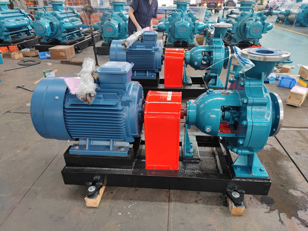
- Commodity name: IH Type OH1 Horizontal Single-stage Chemical Centrifugal Pump
Flow Range: 6.3~400 m3/h</br> Head Range: 5~125 m</br> Fluid Temperature: -20~150 ℃ (Please specify if higher than 80℃)</br> Inlet Pressure: 0~7.5 MPa (Please specify if higher than 0.4 MPa)</br> Shaft Seal: packing seal, mechanical seal</br> Available Materials: HT200, HT250, QT600, ZG, 304, 316, 316L, 317L, 904L, CD</br></br></br></br>
IH type single-stage single-suction cantilever chemical centrifugal pump is an energy-saving upgraded product replacing F-type corrosion-resistant centrifugal pumps. It is widely applied in chemical, petroleum, metallurgical, papermaking, food, pharmaceutical, synthetic fiber and other industrial sectors, for conveying corrosive liquids or contamination-sensitive liquids with viscosity similar to water. The inlet pressure of the pump shall not exceed 0.3 MPa.
The temperature of conveyed medium is generally between -20℃ and 105℃. With proper cooling measures adopted when necessary, the pump can handle liquids at higher temperatures.
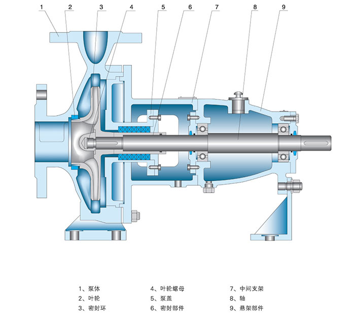
Structure Description
Main components include pump casing, impeller, wear ring, impeller nut, pump cover, sealing assembly, intermediate bracket, shaft and bearing bracket.
Structural Features
The pump cover is fixed to the intermediate bracket via spigots, and clamped in place by the connection between the pump casing and the intermediate bracket spigots. The pump casing adopts axial suction, radial discharge and foot-mounted design, which can be directly installed on the base. The bearing bracket assembly is fastened to the intermediate bracket with spigots and supported on the base by the bearing support.
During maintenance, there is no need to disconnect inlet and outlet pipelines, disassemble the pump casing or motor. Simply remove the intermediate connector of the extended coupling, then the rotor assembly can be pulled out for servicing.
There are 9 types of shaft seals including packing seal and mechanical seal, which can be selected according to the properties of conveyed medium and production process requirements.
The pump is connected to the motor via an extended coupling. Viewed from the drive end, the pump rotates clockwise.
Model Description
Example: IH80-65-160A-304
IH -- International standard chemical pump
80 -- Suction diameter: 80 mm
65 -- Discharge diameter: 65 mm
160 -- Nominal diameter of impeller: 160 mm
A -- Impeller diameter trimming code (A for the first trimming, B for the second trimming)
304 -- Material code for liquid-contact parts: ZG0Cr18Ni9
-
Flow Range: 6.3~400 m3/h
Head Range: 5~125 m
Fluid Temperature: -20~150 ℃ (Please specify if higher than 80℃)
Inlet Pressure: 0~7.5 MPa (Please specify if higher than 0.4 MPa)
Shaft Seal: packing seal, mechanical seal
Available Materials: HT200, HT250, QT600, ZG, 304, 316, 316L, 317L, 904L, CD
-
-
Disassembly and Assembly
1. To inspect or replace the impeller, close the outlet valve, remove flange bolts and base plate bolts, then lift the pump out of the container with lifting equipment.
2. Place the base plate on the support, remove all bolts of the pump casing, take out the pump cover and impeller nut. Tap the pump casing gently with two hammers to detach the impeller.
3. For replacement of rolling bearings or packing, keep the base plate in place. Remove the motor and corresponding brackets first, then take off the pump coupling, gland and round nut, and extract the bearing housing. To replace packing, remove the packing gland before taking out and installing new packing.
4. Assembly shall be performed in the reverse order of disassembly. Ensure the concentricity of all components mounted on the shaft.
Installation, Operation and Maintenance
1. After assembly, turn the coupling manually to check for flexible rotation. Listen for metal friction noise and verify all nuts are fully tightened.
2. Check the concentricity between the pump shaft and motor shaft. The radial runout of the two couplings shall not exceed 0.1 mm, and the end face clearance between them shall be kept at 1~2.5 mm.
3. The distance from the pump suction port to the container bottom shall be 2 to 3 times the suction port diameter. The clearance between the pump casing and container wall shall be more than 2.5 times the port diameter.
4. The discharge pipeline shall be supported by separate brackets. The pipeline weight shall not be borne by the pump.
5. Check the motor rotation direction to ensure the pump runs as marked.
6. Close the gate valve and pressure gauge on the discharge pipeline, and connect the cooling water pipe.
7. Start the motor, turn on the pressure gauge, then slowly open the discharge gate valve to the required position for normal operation.
8. Inspect the pump and motor regularly. The temperature rise of bearings shall not exceed 75℃, and sufficient grease shall be filled in the bearing housing.
-
Pump fails to start
1. Power failure: Check the power switch and circuits.
2. Motor wiring fault: Inspect motor connections.
3. Internal blockage: Check for foreign objects inside the pump.
4. Motor failure: Check if the motor is damaged.
Reduced water output
1. Air leakage in pump chamber: Inspect shaft seals, sealing rings and valves for damage.
2. Air leakage at inlet valve: Check the valve sealing ring for damage.
3. Foreign matter, friction or blockage inside pump chamber: Remove foreign objects and clean deposits inside the pump.
Excessive operating noise
1. Loose connection between pump base and support: Reinstall or replace the support bracket.
2. Poor fitting between pump chamber and pump body: Adjust the axial clearance to ensure tight contact.
3. Damaged bearings or foreign matter ingress: Replace the bearings.
Excessive pump temperature
1. Pump burnout: Inspect the pump for damage and replace defective components.
2. Damaged bearings or inadequate lubrication: Check bearings and lubrication system, replace faulty bearings and maintain proper lubrication.
The above are common faults and corresponding solutions for submerged pumps. Regular maintenance is recommended during operation. Timely troubleshooting shall be performed according to actual conditions to extend the pump service life and ensure production safety.
Previous Page
Next Page
Customer Case
Product Consulting
If you are interested in our products, please leave your email, we will contact you as soon as possible, thank you!


Hunan Sanchang Pump Co., Ltd.
| Email: | info@sanchangpump.net |
| Hotline: | +86 181 4266 2779 |
| +86 193 1300 1794 | |
| Mobile/Wechat/WhatsApp: | +86 181 4266 2779 |
| Address: | No.517,Xiangfu Road, Yuhua |
| District, Changsha City | |
| Hunan Province, P.R.C |
