
Products
Recommend Products
Contact Us
| Email: | info@sanchangpump.net |
| Hotline: | +86 181 4266 2779 |
| +86 193 1300 1794 | |
|
Wechat: |
+86 181 4266 2779 |
|
WhatsApp: |
+86 181 4266 2779 |
| Address: | No.517,Xiangfu Road |
| Yuhua District, | |
| Changsha City | |
| Hunan Province, P.R.C |

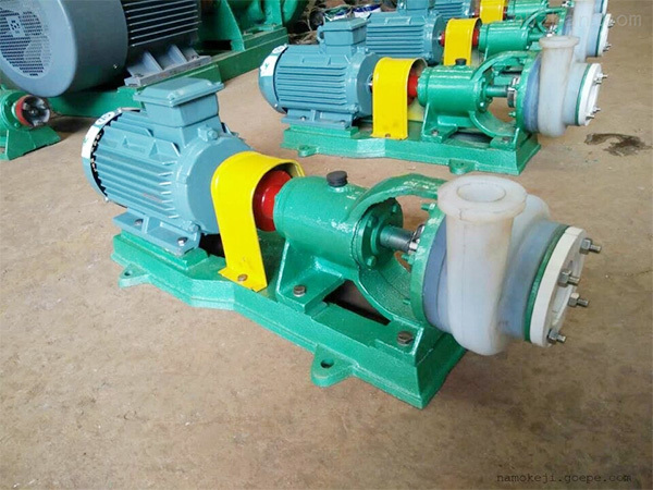
FSB Type Fluoroplastic Corrosion-resistant Pump
Classification:
End Suction Centrifugal Pump
Petrochemical Industry
Salt Chemical Industry
Key words:
Corrosion-resistant Pump
Fluoroplastic Chemical Pump
OH2 Pump
Hotline:
- Product Description
- Performance Parameter
- Installation Drawings
- Installation And Use
- Faults And Solutions
-
- Commodity name: FSB Type Fluoroplastic Corrosion-resistant Pump
Flow Range: 3.6~100 m³/h</br> Head Range: 15~55 m</br> Rotational Speed: 2900 r/min</br> Power: 1.5~18.5 kW</br> Inlet Diameter: 25~100 mm</br> Applicable Temperature: -20℃~120℃</br> Inlet Pressure: ≤ 0.3 MPa (Please specify if exceeding 0.3 MPa)</br> Shaft Seal: mechanical seal</br> Pump Material: fluoroplastic</br></br>
Product Description
FSB type fluoroplastic corrosion-resistant pump is designed in accordance with international standards. The pump casing features a metal outer shell lined with fluorinated ethylene propylene (F46). The pump cover, impeller and shaft sleeve are integrally sintered and pressed with metal inserts coated with fluoroplastic. It adopts externally mounted bellows mechanical seal. The stationary ring is made of 99% alumina ceramic or silicon nitride, and the rotating ring uses PTFE filled material. Featuring excellent corrosion and wear resistance, the pump is applicable for conveying highly corrosive media under harsh working conditions, including sulfuric acid, hydrochloric acid, acetic acid, hydrofluoric acid, nitric acid, aqua regia, strong alkalis, strong oxidants, organic solvents and reducing agents of any concentration. It ranks among the top high corrosion-resistant equipment worldwide.
Overview
This series is a single-stage single-suction cantilever centrifugal pump. All flow passage components are made of fluoroplastic. Lining materials including fluorinated ethylene propylene (F46) and polyvinylidene fluoride (F2) are available for selection as required.
It is mainly used to deliver clear liquids such as acids, alkalis and solvents. Equipped with special seals, it can also convey corrosive media containing a small amount of solid particles. This pump series is fitted with mechanical seals of WB2, 152, 169 types, with an operating temperature range of -20℃ to 100℃.
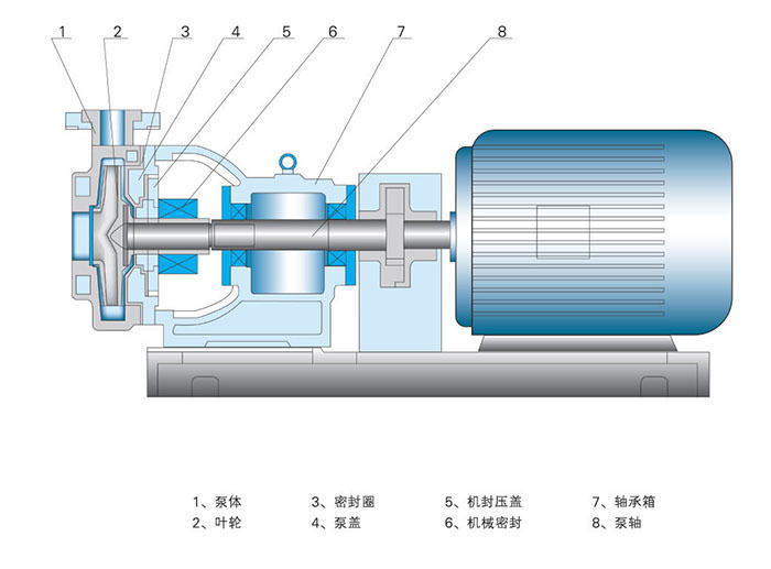
Structure Description
FSB type fluoroplastic corrosion-resistant pump consists of pump casing, impeller, pump cover, sealing assembly, bracket, pump shaft, coupling, tightening bolts, nuts and base plate.
1. Pump Casing: Each connecting end is embedded with a steel flange ring, and integrally molded with plastic alloy.
2. Pump Cover: One side is embedded with 1Cr18Ni9Ti stainless steel and molded with plastic alloy.
3. Impeller: Connected via a coupling shaft. The high-precision machined high-grade steel shaft is externally molded with plastic alloy, forming a solid integral structure with the impeller. This design enables the shaft root and rear part of the impeller to bear rotational torque, and ensures all wetted parts are made of plastic alloy.
4. Mechanical Seal: Adopts WB2 and ST types of adjustable face seals requiring no cooling water, manufactured from silicon carbide, high-purity alumina ceramic, filled PTFE and graphite.
Application
Widely used for liquid transportation in chemical, petroleum, pharmaceutical, pesticide, dyestuff, coating, smelting, papermaking, electroplating, food, pickling and other industries. It effectively eliminates leakage, dripping and overflow, making it an ideal facility for standardized and civilized factories.
1. Acid-resistant Type: For conveying various strong acids or mixtures of acids and solvents.
2. Alkali-resistant Type: For conveying clear alkaline liquids or mixtures of alkalis and solvents.
3. Solid Particle Resistant Type: For acidic or alkaline liquids containing a small quantity of solid particles. For media with high solid content, please select CUHB-ZK series corrosion-resistant slurry pumps or contact our company for model selection.
4. Explosion-proof Type: For flammable and explosive liquids, matched with explosion-proof motors.
5. Operating Condition Sheet: If you have difficulty in model selection, please fill in the operating condition sheet and send it to our company via fax or mail for professional selection assistance.
Model Description
Example: 50FSB(L)-25
50 -- Inlet diameter of the pump: 50 mm
FSB -- Flow passage components made of fluoroplastic
L -- Direct-coupled structure (No L indicates bracket-type structure)
25 -- Rated head: 25 m
-
Flow Range: 3.6~100 m³/h
Head Range: 15~55 m
Rotational Speed: 2900 r/min
Power: 1.5~18.5 kW
Inlet Diameter: 25~100 mm
Applicable Temperature: -20℃~120℃
Inlet Pressure: ≤ 0.3 MPa (Please specify if exceeding 0.3 MPa)
Shaft Seal: mechanical seal
Pump Material: fluoroplastic
-
-
Disassembly
1. The pump is connected to the motor via a jaw coupling. First loosen the four bolts fastening the bracket to the base to separate the pump from the motor.
2. Remove the bolts of the pump rear cover, then tap the pump casing gently with a wooden mallet to detach it.
3. Loosen the tightening bolt inside the coupling where the impeller shaft and pump shaft are connected by a Morse taper.
4. Undo the set screws of the mechanical seal rotating ring. Tap the central tightening bolt of the coupling lightly with a wooden mallet. After the impeller shaft is separated from the pump shaft, pull out the impeller, rear cover and rotating ring of the seal. Loosen the gland screws on the rear cover and take out the stationary ring.
5. Remove the screws of the left and right shaft glands, take out the pump shaft and bearings, and clean the oil chamber of the bracket.
Assembly
Install the seal rotating ring, stationary ring, rear cover, gland, impeller and pump casing in the reverse order of disassembly, and fasten all set bolts securely.
Installation and Precautions
1. Inspect the pump and motor before installation to ensure all parts are intact and no foreign objects remain inside the pump.
2. Place the pump horizontally, connect the inlet and outlet pipelines and power supply. Rotate the coupling manually to check for friction. The installation is completed if the coupling turns smoothly and evenly.
3. Plastic alloy centrifugal pumps have lower rigidity than metal pumps. The weight of pipelines shall not be borne by the pump casing; separate supports must be fitted for inlet and outlet pipes. For high-head pumps, install a check valve on the outlet pipeline to prevent water hammer damage caused by sudden shutdown.
4. Ensure all joints are well sealed to avoid air or liquid leakage, which may impair pump performance.
5. Immediately stop operation if abnormal vibration or noise occurs. Resume use only after troubleshooting.
Start-up and Shutdown
1. Prime the pump with sufficient liquid.
2. Check that the oil level in the bracket oil chamber is within the specified range.
3. Verify the motor rotation direction against the rotation marking on the pump.
4. Close the outlet valve and pressure gauge cock.
5. Start the motor, open the pressure gauge cock, then slowly open the outlet valve. Adjust the valve until the pressure gauge reads the required value.
6. For normal shutdown, close the outlet valve first, then cut off the power supply.
-
Failure to discharge liquid during operation & Solutions
1. Insufficient liquid in pump chamber (air not fully vented).Solution: Refill liquid until the pump chamber is completely full.
2. Incorrect rotation direction upon startup.Solution: Check the running direction of the matched motor.
3. Excessively low rotating speed after startup.Solution: Stop the pump to inspect the motor speed, and replace the motor with appropriate power and speed.
4. Blocked inlet filter screen.Solution: Inspect the filter screen and remove debris.
5. Suction lift exceeds the rated value, resulting in vacuum in the liquid tank.Solution: Reduce the suction lift and check the pressure of the liquid tank.
Intermittent liquid discharge & Solutions
1. Air leakage in the inlet pipeline.Solution: Inspect pipe joints and packing seals for air leakage.
2. Residual air in the inlet during pump priming.Solution: Reprime the pump.
3. Inlet blocked by foreign matters.Solution: Shut down the pump and clear the blockage.
4. Large volume of air sucked in from the inlet.Solution: Check for vortexes at the suction port and verify sufficient submergence depth.
Excessive vibration & Solutions
1. Large misalignment between pump shaft and motor shaft.Solution: Realign the two shafts.
2. Excessive suction lift causing cavitation.Solution: Lower the installation height.
3. Mechanical friction inside the pump.Solution: Locate the worn parts and carry out maintenance.
Customer Case
Product Consulting
If you are interested in our products, please leave your email, we will contact you as soon as possible, thank you!


Hunan Sanchang Pump Co., Ltd.
| Email: | info@sanchangpump.net |
| Hotline: | +86 181 4266 2779 |
| +86 193 1300 1794 | |
| Mobile/Wechat/WhatsApp: | +86 181 4266 2779 |
| Address: | No.517,Xiangfu Road, Yuhua |
| District, Changsha City | |
| Hunan Province, P.R.C |
