
Products
Recommend Products
Contact Us
| Email: | info@sanchangpump.net |
| Hotline: | +86 181 4266 2779 |
| +86 193 1300 1794 | |
|
Wechat: |
+86 181 4266 2779 |
|
WhatsApp: |
+86 181 4266 2779 |
| Address: | No.517,Xiangfu Road |
| Yuhua District, | |
| Changsha City | |
| Hunan Province, P.R.C |

IHF Type Corrosion-resistant Fluoroplastic Chemical Pump
Classification:
End Suction Centrifugal Pump
Petrochemical Industry
Metallurgical Industry
Key words:
Chemical Pump
Fluoroplastic Chemical Pump
Corrosion-resistant Pump
Hotline:
- Product Description
- Performance Parameter
- Installation Drawings
- Installation And Use
- Faults And Solutions
-
- Commodity name: IHF Type Corrosion-resistant Fluoroplastic Chemical Pump
Flow Range: 1.75~130 m3/h</br> Head Range: 5~87 m</br> Fluid Temperature: -20~105 ℃</br> Inlet Pressure: 0~0.3 MPa</br> Shaft Seal: packing seal, mechanical seal</br> Available Materials: HT200, HT250, QT600, ZG, 304, 316, 316L, 317L, 904L, CD4-MCu, etc</br></br></br>
The IHF type fluoroplastic chemical centrifugal pump is a single-stage single-suction pump made of fluoroplastic alloy. It is designed and manufactured in compliance with national standards combined with the processing technology of non-metallic pumps.
This pump features excellent corrosion resistance, wear resistance, high temperature resistance, anti-aging performance, high mechanical strength and no toxic decomposition. It supports a wide operating temperature range from -85℃ to 200℃. It is widely applied for liquid delivery, wastewater treatment, acid dosing and other processes in chemical, pharmaceutical, petroleum, metallurgical, electric power, electroplating, pickling, pesticide, papermaking and other industries.
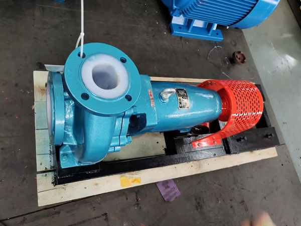
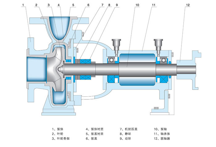
Structural Features
The pump casing adopts a metal shell lined with fluorinated ethylene propylene (F46). The impeller and pump cover are integrally sintered and pressed with metal inserts coated with fluoroplastic. The shaft seal is an externally mounted bellows mechanical seal. The stationary ring is made of 99.9% alumina ceramic or silicon carbide, and the rotating ring is made of filled PTFE or silicon carbide.
With advanced and reasonable structure, this pump delivers outstanding corrosion resistance, tight and reliable sealing, stable operation, low noise and long service life.
Main Applications
It is suitable for conveying highly corrosive media of any concentration, including sulfuric acid, hydrochloric acid, nitric acid, acetic acid, hydrofluoric acid, strong alkalis, strong oxidants and organic solvents. It is one of the advanced corrosion-resistant pumps available on the market.
Model Description
Example: IHF80-65-160A;
IH -- Code for international standard chemical pump series
F -- Flow passage components made of fluoroplastic
80 -- Inlet diameter: 80 mm
65 -- Outlet diameter: 65 mm
160 -- Nominal impeller diameter: 160 mm
A -- Impeller with first diameter trimming
-
Flow Range: 1.75~130 m3/h
Head Range: 5~87 m
Fluid Temperature: -20~105 ℃
Inlet Pressure: 0~0.3 MPa
Shaft Seal: packing seal, mechanical seal
Available Materials: HT200, HT250, QT600, ZG, 304, 316, 316L, 317L, 904L, CD4-MCu, etc
-
-
Disassembly and Assembly
1. To inspect or replace the impeller, close the outlet valve, remove the flange bolts and base plate bolts, then lift the pump out of the container with lifting equipment.
2. Place the base plate on the support bracket. Remove all bolts of the pump casing, take out the pump cover and impeller nut. Gently strike the pump casing with two hammers to detach the impeller.
3. For replacement of rolling bearings or packing, keep the base plate fixed. Remove the motor and corresponding brackets first, then take off the pump coupling, gland and round nut, and extract the bearing housing. To replace the packing, remove the packing gland before taking out the old packing and installing the new one.
4. Perform assembly in the reverse order of disassembly. Strictly ensure the concentricity of all components mounted on the shaft.
Installation, Operation and Maintenance
1. After assembly, rotate the coupling manually to check for flexible movement. Listen for metal friction noise and confirm all component nuts are fully tightened.
2. Check the concentricity between the pump shaft and motor shaft. The radial runout of the two couplings shall not exceed 0.1 mm, and the end face clearance between them shall be maintained at 1~2.5 mm.
3. The distance from the pump suction port to the container bottom shall be 2 to 3 times the suction port diameter. The clearance between the pump casing and container wall shall be more than 2.5 times the port diameter.
4. The discharge pipeline shall be supported by independent brackets. The pipeline weight is not allowed to bear on the pump.
5. Verify the motor rotation direction to ensure the pump rotates as marked.
6. Close the gate valve and pressure gauge on the discharge pipeline, and connect the cooling water pipe.
7. Start the motor, turn on the pressure gauge, then slowly open the discharge gate valve to the required position for normal operation.
8. Inspect the pump and motor regularly. The temperature rise of bearings shall not exceed 75℃, and sufficient grease shall be filled in the bearing housing.
-
Pump Fails to Start
1. Power failure: Check the power switch and circuits.
2. Motor wiring fault: Inspect the motor connections.
3. Internal blockage: Check for foreign objects inside the pump.
4. Motor malfunction: Verify whether the motor is damaged.
Reduced Water Output
1. Air leakage in the pump chamber: Inspect the shaft seal, sealing rings and valves for damage.
2. Air leakage of the inlet valve: Check if the valve sealing ring is damaged.
3. Foreign matter, friction or blockage inside the pump chamber: Remove foreign objects and clean deposits inside the pump.
Excessive Operating Noise
1. Loose fit between pump base and support bracket: Reinstall or replace the bracket.
2. Poor contact between pump chamber and pump body: Adjust the axial clearance to ensure tight connection.
3. Damaged bearings or ingress of foreign matter: Replace the bearings.
Excessive Pump Temperature
1. Pump burnout: Inspect the pump for damage and replace faulty components.
2. Damaged bearings or insufficient lubrication: Check the bearings and lubrication system, replace defective bearings and maintain proper lubrication.
The above are common faults and corresponding solutions for submerged pumps. Regular maintenance is required during operation. Please troubleshoot faults in a timely manner according to actual conditions, so as to extend the service life of the pump and ensure production safety.
Previous Page
Next Page
Customer Case
Product Consulting
If you are interested in our products, please leave your email, we will contact you as soon as possible, thank you!


Hunan Sanchang Pump Co., Ltd.
| Email: | info@sanchangpump.net |
| Hotline: | +86 181 4266 2779 |
| +86 193 1300 1794 | |
| Mobile/Wechat/WhatsApp: | +86 181 4266 2779 |
| Address: | No.517,Xiangfu Road, Yuhua |
| District, Changsha City | |
| Hunan Province, P.R.C |
