
Products
Recommend Products
Contact Us
| Email: | info@sanchangpump.net |
| Hotline: | +86 181 4266 2779 |
| +86 193 1300 1794 | |
|
Wechat: |
+86 181 4266 2779 |
|
WhatsApp: |
+86 181 4266 2779 |
| Address: | No.517,Xiangfu Road |
| Yuhua District, | |
| Changsha City | |
| Hunan Province, P.R.C |

IS Type Horizontal Single-stage Single-suction Centrifugal Pump
Classification:
End Suction Centrifugal Pump
Petrochemical
Urban Water Supply
Mining
Key words:
Single-stage Pump
Horizontal Centrifugal Pump
Water Pump


Hotline:
- Product Description
- Performance Parameters
- Installation Drawings
- Installation and Operation
- Faults and Solutions
-
- Commodity name: IS Type Horizontal Single-stage Single-suction Centrifugal Pump
Flow Range: 6.3~400 m3/h</br> Head Range: 5~125 m</br> Fluid Temperature: -20~150 ℃</br> Inlet Pressure: 0~7.5 MPa</br> Shaft Seal: packing seal, mechanical seal</br> Available Materials: HT200, HT250, QT600, ZG, 304, 316, 316L, 317L, 904L, CD4-MCu, etc</br></br></br>
IS type horizontal single-stage single-suction centrifugal pump is designed for transporting clean water or liquids with physical and chemical properties similar to clean water, with the medium temperature not exceeding 80℃.
Structural Features
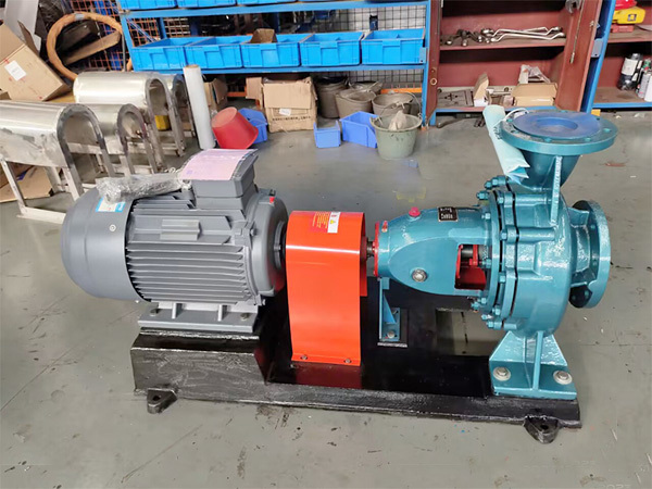
It adopts horizontal installation with horizontal axial suction and vertically upward discharge port. For IY type pumps, the discharge port can be oriented rightward, leftward or upward when viewed from the suction side.
The rotor assembly can be removed for maintenance without detaching the inlet and outlet pipelines. Gland packing seal or mechanical seal is available for shaft seal selection according to operating conditions. Various materials including ordinary cast iron, wear-resistant cast iron, cast steel and cast stainless steel are optional for different working conditions.
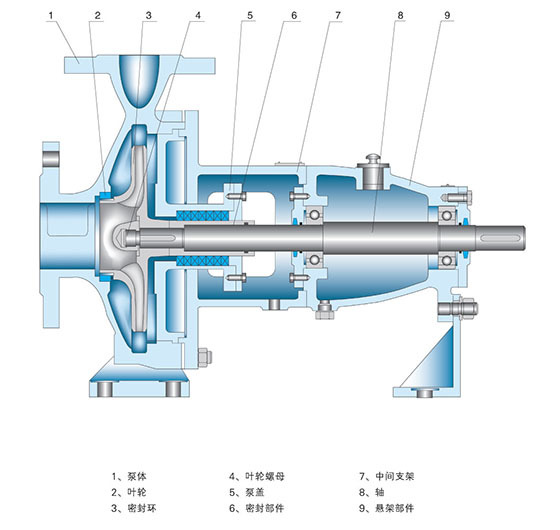
The pump cover is fixed to the intermediate bracket via spigot joints, and clamped in place by the connection between the pump body and the intermediate bracket through spigots. The pump body features axial suction and radial discharge with foot mounting structure, which can be directly fixed on the base. The suspension component is mounted on the intermediate bracket via spigots and supported on the base by the suspension stand.During maintenance, there is no need to remove inlet & outlet pipelines, pump body or motor. Simply detach the intermediate coupling part of the extended coupling, then the rotor assembly can be pulled out for inspection and repair.
Main Components
Main parts: pump body, impeller, wear ring, impeller nut, pump cover, sealing assembly, intermediate bracket, shaft and suspension, etc.
Rotation Direction
The pump is connected to the motor via flexible coupling. It rotates clockwise when viewed from the drive end.
Model Description
For example: IS80-65J-125A
IS -- Clean water pump
80 -- Inlet diameter of the pump, 80 mm
65 -- Outlet diameter of the pump, 65 mm
J -- Reduced speed operation
125 -- Nominal diameter of impeller
A -- First trimming of impeller
-
Flow Range: 6.3~400 m3/h
Head Range: 5~125 m
Fluid Temperature: -20~150 ℃
Inlet Pressure: 0~7.5 MPa
Shaft Seal: packing seal, mechanical seal
Available Materials: HT200, HT250, QT600, ZG, 304, 316, 316L, 317L, 904L, CD4-MCu, etc
-
-
Start-up and Operation
1. Turn the motor fan blade manually. The impeller shall rotate freely without jamming or friction.
2. Rotate the pump by hand to feed lubricant to the mechanical seal faces.
3. Prime the pump and vent air. Open the inlet valve to fully fill the pump casing and pipelines with liquid, and ensure tightness of the inlet pipeline.
4. Close the outlet valve to reduce starting current.
5. Switch on the power and perform inching start to verify the correct rotation direction. The pump shall rotate clockwise when viewed from the motor fan end.
6. Gradually open the outlet valve, and keep the pump operating under rated conditions as far as possible.
7. Stop the pump immediately for inspection if abnormal noise is heard during operation.
8. Normal leakage of mechanical seal shall be less than 3 drops per minute. Check the motor; the temperature rise of bearings shall be lower than 70℃. Investigate the cause if exceeding the limit.
Shutdown
1. Close the discharge pipeline valve.
2. Cut off the power supply to stop the motor.
3. Close the inlet valve.
4. Drain all liquid inside the pump if it will be out of service for a long time.
-
Fault Symptom Cause of Fault Troubleshooting Method 1. Pump does not deliver water a. Inlet/outlet valves not open, blocked pipelines, or blocked impeller flow passage.
b. Wrong motor rotation direction, or slow speed due to motor phase loss.
c. Air leakage in the suction pipe.
d. Pump not fully primed, air trapped in the pump chamber.
e. Insufficient inlet water supply, excessive suction lift, or foot valve leakage.
f. Excessive pipeline resistance or improper pump selection.
a. Inspect and remove blockages.
b. Correct motor rotation direction and tighten wiring connections.
c. Tighten all sealing surfaces to eliminate air leakage.
d. Fill the pump with liquid, open the vent valve to purge all air.
e. Shut down the pump for inspection and adjustment (this often occurs when connected to municipal water lines or used with high suction lift).
f. Reduce pipeline elbows and select a more suitable pump.
2. Insufficient pump flow a. First check causes listed in Item 1.
b. Partial blockage in pipelines/pump flow passages/impeller, scale buildup, or insufficient valve opening.
c. Low voltage.
d. Impeller wear.
a. First follow troubleshooting steps in Item 1.
b. Remove blockages and readjust valve opening.
c. Stabilize the voltage.
d. Replace the impeller.
3. Excessive power consumption a. Operating beyond rated flow.
b. Excessive suction lift.
c. Worn pump bearings.
a. Adjust flow rate by partially closing the outlet valve.
b. Reduce the suction lift.
c. Replace the bearings.
4. Noise and Vibration
a. Unstable pipeline supports.
b. Gas entrained in liquid.
c. Cavitation occurs.
d. Damaged bearings.
e. Motor operates under overload and overheats.
a. Secure the pipelines.
b. Increase suction pressure and vent gas.
c. Reduce vacuum level.
d. Replace bearings.
e. Adjust according to Item 5.
5. Motor Overheating
a. Excessive flow rate leading to overload operation.
b. Mechanical friction and interference.
c. Damaged motor bearings.
d. Insufficient voltage.
a. Throttle the outlet valve.
b. Inspect and eliminate faults.
c. Replace bearings.
d. Stabilize voltage.
6. Water Pump Leakage
a. Worn mechanical seal.
b. Sand holes or cracks on pump body.
c. Uneven sealing surface.
d. Loose mounting bolts.
a. Replace the component.
b. Weld repair or replace the pump body.
c. Refinish the sealing surface.
d. Tighten the bolts.
Customer Case
Send Inquiry
If you are interested in our products, please leave us a message and we will reply to you as soon as possible, thank you!



Hunan Sanchang Pump Co., Ltd.
| Email: | info@sanchangpump.net |
| Hotline: | +86 181 4266 2779 |
| +86 193 1300 1794 | |
| Mobile/Wechat/WhatsApp: | +86 181 4266 2779 |
| Address: | No.517,Xiangfu Road, Yuhua |
| District, Changsha City | |
| Hunan Province, P.R.C |
