
Recommend Products
Contact Us
| Email: | info@sanchangpump.net |
| Hotline: | +86 181 4266 2779 |
| +86 193 1300 1794 | |
|
Wechat: |
+86 181 4266 2779 |
|
WhatsApp: |
+86 181 4266 2779 |
| Address: | No.517,Xiangfu Road |
| Yuhua District, | |
| Changsha City | |
| Hunan Province, P.R.C |

Mobile Permanent Magnet Pump for Waterlogging Rescue / Irrigation
Classification:
Sewage pump
Urban water supply
Key words:
Sewage Pump
Urban Water Supply
Permanent Magnet Pump
Head Range: ~ 80 m
Hotline:
- Product Description
- Performance Parameter
- Installation Drawings
- Installation And Use
- Faults And Solutions
-
- Commodity name: Mobile Permanent Magnet Pump for Waterlogging Rescue / Irrigation
Flow Range: 100 ~ 1000 m ³/h<br> Head Range: ~ 80 m<br /></br><br /></br><br /></br><br /></br>
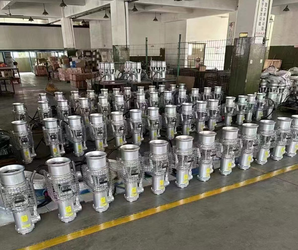
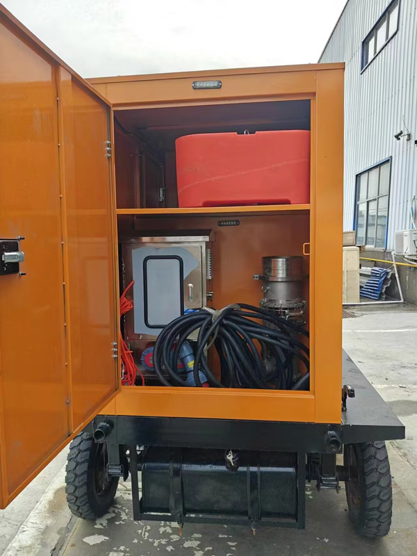
High-Speed axial flow pump with permanent magnet synchronous motor is one of our utility model patents. Our company holds 20 utility model patents for permanent magnet synchronous motor pumps, as well as an invention patent for the High-Speed Deep Well Pump.This permanent magnet synchronous axial flow pump features high efficiency, light weight and compact size, weighing only a quarter of conventional axial flow pumps. It delivers large flow rate and is easy to transport. Equipped with water hoses and quick flange couplings, it is ideal for flood control and emergency drainage, water pumping for subways, bridges and culverts, as well as drainage of basements and parking garages. It is particularly suitable for manual handling for irrigation and drainage, and small vehicle-mounted flood relief operations.
The pump is equipped with automatic protection against overvoltage, overcurrent and phase loss. It will shut down automatically within one minute when pumping is finished, effectively protecting the motor windings from burnout. It is an intelligent axial flow pump.
Pump Unit
This axial flow pump adopts a permanent magnet synchronous motor and is part of our independently developed pump series. Its impellers and flow passages are professionally designed by experts from water conservancy research institutions, delivering excellent performance.
As a patented product covered by our invention and utility model patents, the pump achieves an overall efficiency of up to 60%, leading the industry and nearly 20% higher than many similar products on the market. Third-party test reports issued by provincial and ministerial-level institutions are available. We provide models with flow rates of 200, 500, 800 and 1000 cubic meters per hour. We are a reliable supplier with proprietary patented technology and a complete range of specifications.
Built-in protection against overheating, overcurrent and overload prevents damage to motor windings. The impellers and pump shaft are made of precision-cast stainless steel. The pump body is available in aluminum alloy and stainless steel. Cable terminals are protected by rubber sleeves and stainless steel springs for high safety and reliability.8-inch outlet: DN200 quick coupling;10-inch outlet: DN250 quick coupling;12-inch outlet: DN300 quick coupling.All couplings are fitted with hose clamps for easy connection and disconnection of water hoses. The standard configuration includes a 20-meter power cable, and customized longer cables are available on request.
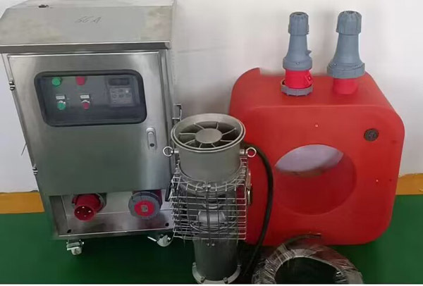
Control System
Matched with a frequency converter, the system can display operating frequency, voltage and current in real time. It supports automatic protection against overheating, overcurrent and overload, as well as automatic shutdown under dry-run conditions.
Remote control is accessible via 3G/4G mobile networks. Users can remotely transmit data, start or stop the pump and adjust its operating speed through computers and mobile devices. This remote control function is an optional extra.We offer single-pump and one-drive-two control cabinets with optional IP44 or IP54 protection ratings. Waterproof plugs and sockets for 3-phase 4-wire power supply come as standard to ensure safe and stable operation.
For fixed drainage applications such as bridges, culverts, basements and parking garages, the system can work automatically. It starts pumping when the water level reaches the preset height, and switches to standby or shuts down when the water level drops below the pump inlet.
After-sales Service
We provide a 1-year warranty with free maintenance service within the warranty period. For faults that cannot be resolved by phone consultation, our local distributors will offer on-site support. Service technicians will arrive at the site on the same day within 500 kilometers nationwide, and within two days for locations over 500 kilometers away.
-
Flood control pump specification parameter table
Pump type
Model
Rated flow
T/hRated lift
MMotor power
KWExport caliber inch
Net pump weight
KGOverall dimension
mm
Remarks
Big
Stream
Quantity
Anti-
Flood
Pump6SZQ250-8-11
250
8
11
6
21
250*280*570
8SZQ470-7-15
470
7
15
8
26/38
250*280*570
8SZQ480-8-18.5
480
8
18.5
8
29/39
250*280*570
8SZQ500-10-22
500
10
22
8
31/41
250*280*570
8SZQ500-12-27
500
12
27
8
32/42
250*280*570
10SZQ600-12-30
600
12
30
10
49
280*280*680
10SZQ800-10-37
800
10
37
10
50
280*280*680
12SZQ1000-8-37
1000
8
37
12
70
380*380*820
12SZQ1000-10-45
1000
10
45
12
78
380*380*820
12SZQ800-15-55
800
15
55
12
80
380*380*820
ground
Iron
Use
High
Jan
Cheng
Anti-
Flood6SZW100-50-22
100
50
22
6
31/41
230*230*580
6SZW150-32-22
150
32
22
6
31/41
230*230*580
6SZW200-45-37
200
45
37
6
42/49
280*280*700
6SZW200-55-45
200
55
45
6
44/51
280*280*700
8SZW300-18-22
300
18
22
8
31/41
230*230*580
8SZW300-23-30
300
23
30
8
32/43
230*230*580
8SZW300-30-37
300
30
37
8
43/50
280*280*700
8SZW300-40-55
300
40
55
8
76
380*380*740
8SZW300-50-75
300
50
75
8
83
380*380*740
8SZW400-20-37
400
20
37
8
51
280*280*700
8SZW400-30-55
400
30
55
8
78
380*380*780
8SZW400-40-75
400
40
75
8
83
380*380*800
8SZW400-50-95
400
50
95
8
86
380*380*800
8SZW400-60-110
400
60
110
8
125
420*420*1300
8SZW400-70-130
400
70
130
8
155
420*420*1500
8SZW400-80-150
400
80
150
8
210
450*450*1600
8SZW500-20-45
500
20
45
8
70
380*380*780
8SZW500-25-55
500
25
55
8
73
380*380*780
8SZW500-35-75
500
35
75
8
83
380*380*800
8SZW500-45-95
500
45
95
8
86
380*380*800
8SZW500-50-110
500
50
110
8
125
420*420*1300
8SZW500-60-130
500
60
130
8
155
420*420*1500
dual-use pump
8SZQ-HL-22
500
32
22
8
45
280*280*580
10SZQ-HL-30
600
30
37
10
60
280*280*700
downdraw
8SZQ500-9-22L
500
9
22
8
45
310*310*750
8SZQ600-10-30L
600
10
30
8
54
400*400*8500
10SZQ800-9-37L
800
9
37
10
56
400*400*850
Electrical cabinet weight: 15KW,31.6kg 22kw35.8kg,30kw44.6kg,37kw46.6kg,45kw62kg,55kw71kg.
The complete set includes: pump main machine (cable standard 20 m), domestic variable frequency drive, stainless steel electrical cabinet assembly, 1 pair of quick connectors, 1 hose clamp, float ball assembly, etc.
-
-
Instructions for use
The high-speed axial flow pump is composed of a pump and a variable frequency drive. The manual in this section focuses on the simple operation of the pump and the variable frequency drive. Generally, this product can be operated and used. If professionals need to adjust the parameters of the variable frequency drive, they should read the instructions for the use of the variable frequency drive (or frequency converter) in detail.
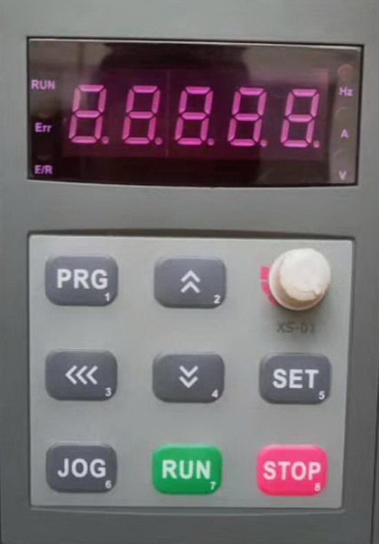
PRG和 JOGIt is programming and functionality with keys, these three keys non-professionals do not touch it.Green RUNis the start key, or power-on key,《 《 《is the display toggle key,The red stop.The key is the stop key, or the shutdown key. The number displayed by the liquid crystal display by default is frequency. The frequency and speed are linear. The frequency is high and the speed is fast, while the frequency is low and the speed is low.Round knob and up and down keysUsed to adjust the frequency (or speed).

These four keys are in the lower part of the panel. The upper row is the power indicator and the running indicator respectively. The next row is the stunning start key and the red stop key respectively.
The variable frequency drive is generally debugged at the factory and does not need to be adjusted separately. Just press the on key or the start and stop keys on the operation panel, and do not press other keys. Do not move the internal wiring of the electrical cabinet easily. Check all the wiring terminals in the cabinet before starting up. If there is any looseness during transportation, tighten the wiring terminals one by one. If you need to adjust, you can only have professional knowledge of frequency converters, and you can adjust the parameters of the variable frequency drive only after carefully reading the variable frequency drive manual and this manual. Otherwise, the variable frequency variable frequency drive program may be confused and can no longer be used, or cause damage.
The three motor lines of the synchronous motor axial flow pump must be connected to the three terminals of the output U V T of the matching variable frequency drive, and cannot be directly connected to the power supply AC380V, otherwise the motor coil will be damaged and the pump will be scrapped. AC380VThe power supply is three-wire connected to the power input of the variable frequency driveR S T On. If it is a three-phase four-wire input of the power grid, do not connect the neutral line.At the incoming end, in case of unbalance of the zero line, there may be potential difference.The problem.
R
S
T
P-
P
P1
U
Words
P-,P, p1Empty, no wiring,One is the grounding wire. In principle, it is connected to the ground wire where it is located, not to the neutral wire of three-phase four-wire.
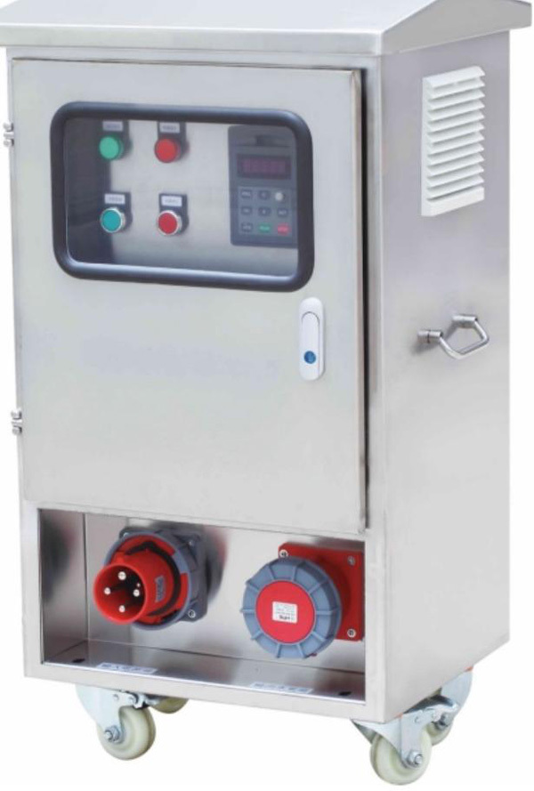
The frequency conversion controller is placed in the stainless steel electrical cabinet, and there are control circuits, cooling fans, circuit breakers, leakage protection, buttons, indicator lights, etc. The electrical cabinet has a rainproof function for outdoor use. In rainy days, attention should also be paid to spray, moisture and moisture.
The electrical cabinet is equipped with a power input socket and an output socket connected to the pump motor. There are notes below the socket for the input power end and the output pump end, which cannot be inserted incorrectly.
After the synchronous motor axial flow pump is equipped with a variable frequency drive, it has automatic protection functions such as overvoltage, overcurrent, overload, and overheating, and works with a wide voltage and keeps the speed synchronized. When there is no water at the pump inlet, the system will automatically detect and determine the entry into the protection program, and automatically shut down to avoid damage to the motor caused by no water cooling.
Each specification of the pump is matched with the corresponding variable frequency drive, the same specification (speed, flow, head and power) pump variable frequency drive can be exchanged, different specifications of the pump can not use the same variable frequency drive, because the motor parameters are not the same, some speed is not the same, can not be exchanged. If it is replaced incorrectly, it will cause damage to the variable frequency drive or pump.
The relationship between the flow, head and power of the axial flow pump is different from the hydraulic model of the centrifugal pump, and there is a big difference. When the axial flow pump used for low lift works at the same output frequency of the variable frequency drive, the lower the lift, the higher the flow rate, the lower the power consumption. If the lift at the work site is relatively low, the working frequency can be appropriately adjusted to set The highest frequency runs to increase the flow rate. However, the higher the lift is used, the greater the input power will be, which can reach 3 times the power at low lift. When the lift is high to a certain extent, when the input power will exceed the rated maximum allowable value, the variable frequency drive will have over-current protection and shut down. At this time, it is necessary to appropriately lower the working frequency of the variable frequency drive, reduce the rotating speed, and appropriately reduce the power to make the working current within the allowable range of the variable frequency drive, this allows the pump to operate normally. But this needs to be done under the operation of skilled staff with inverter expertise.
The rated lift of low-lift axial flow pump is generally 7-10 meters, which is below 15 meters, except for some up to 15 meters. If this low-lift axial flow pump is used for more than 15 meters, it is not appropriate, which will cause high power consumption and low efficiency. If the head is more than 15 meters, the flood control pump with high head should be selected. The pump head with high head is about 20-50 meters, and some are even higher.
In addition, the horizontal length of the water belt connected to the pump outlet is calculated according to the loss lift of 7-10 meters per 100 meters, that is to say, when the length of the water belt transported is 100 meters, it is equivalent to the working lift of 7-10 meters. When the long water belt is connected, if it is more than 200 meters, the actual working lift of the pump will exceed the rated lift, causing the variable frequency drive to stop for protection. At this time, the working current is within the allowable range of the variable frequency drive, so as to ensure the normal operation of the pump. Or re-elect to use high-lift flood pumps.
Instructions for Use
1. The pump is used for drainage, and the depth of water is generally 1-5 meters. Before use, check whether the electric pump is in good condition, whether there is looseness, seepage and oil leakage at each connection, whether there is any accidental damage such as pressure and scratch of cable, etc., and measure the insulation resistance of the electric pump with a megohmmeter, which should be> 50M2 in cold state and> 2M2 in hot state.
2. The pump requires 15% of the power supply voltage. When the output of the variable frequency drive is stable and the voltage is too low, the input current will increase and reach the high setting value of the protection current, causing the variable frequency drive to stop working due to protection. At this time, the manual working state should be used instead, and the pump speed should be lowered a little to reduce the working current and the power.
3. The pump shall be equipped with corresponding electric switch or switch separately. The grounding terminal on the variable frequency drive and the pump housing shall be connected to the ground wire. The yellow and green double-color line in the outgoing line of the electric pump shall be the grounding wire, which must be reliably grounded.
4. The lead wire of the electric pump is strictly prohibited from being pulled to prevent damage to the insulation and cannot be used. When the length of the cable with the belt is not enough and needs to be connected, the wire diameter of the connected wire must be greater than or equal to the original wire diameter. The joint shall be sealed with waterproof adhesive tape.
5. Before the electric pump is officially used, connect the variable frequency drive power supply, press the start key, whether the operation is normal, check whether the rotation direction of the pump impeller is correct, and pay attention to turning for a short time. If the steering of the electric pump is wrong, the water output will clearly show that it is small. Just adjust any two of the three wires from the output terminal of the variable frequency drive to the electric pump. Be careful not to exchange the three wires of the power input to the variable frequency drive. It is useless to exchange the input power cord without changing the direction of rotation.
6. When installing the discharge pump, string ropes at the hole ring. It is strictly prohibited to lift the cable to lift the discharge pump, but it should be more than 1 meter from the bottom of the water to prevent sediment from being sucked and damaging mechanical seals, impellers and other components.
7. When using a floating ball to lift the electric pump, pay special attention to the water level drop, especially when working in the underground, do not run dehydrated, otherwise it will burn out the motor and other components. Can not be put into the bottom of the sludge work, resulting in poor heat dissipation and damage to the pump motor.
-
Pump maintenance and maintenance
1. After the electric pump has been running for 3000 hours, the wearing parts must be replaced once (such as bearings, sealing rings, mechanical seals, cooling lubricating oil, etc.), otherwise the mechanical parts will cause greater losses after damage.
2. If the electric pump is not used for a long time, it should be cleaned and dried. Depending on the peeling of the paint on the surface, it should be placed in a ventilated and dry place for proper storage.
Fault phenomenon
Reason
Solution
Motor does not rotate
Incorrect power supply or inverter drive wiring
The variable frequency drive is in a fault protection state
Pump impeller stuck, motor does not start
Pump motor damaged
Variable frequency drive failureCheck wiring
Check the circuit and variable frequency drive to eliminate the fault
Check the cause of pump card position and eliminate the fault.
If the variable frequency drive, pump motor, bearing, coil and other components are faulty, please contact the maintenance service department.No water from pump or insufficient water
Incorrect impeller steering
Inlet strainer or impeller clogged
Severe wear of impeller
One group or part of the motor coil is damagedExchange the wire from the variable frequency drive output to the pump
Eliminate clogging debris
Replace the impeller and send it to the maintenance department.Diagnosis and Operation Countermeasures of Common Faults of Variable Frequency Drives
Serial Number
Fault code
Fault Type
Possible causes
Simple operation
countermeasures
0.
E-01
Output short circuit
1: Check whether the motor is short-circuited
2: Check whether the wire is damaged
3: slow down too fastP0.17
1: Replace the motor
2: Replace the motor
3: Increase the acceleration time1.
E-02
Accelerated overcurrent
Accelerate too fast
Inverter power is smallP0.16
Increase the acceleration time to increase the inverter power
2.
E-03
deceleration overcurrent
Deceleration too fast
Inverter power is smallP0.17
Increase the deceleration time to increase the inverter power
3.
E-04
Constant speed overcurrent
The motor load suddenly becomes larger
Check whether the motor load is abnormal
4.
E-05 E-06
acceleration overvoltage deceleration overvoltage
Input voltage too high deceleration too fast
Multimeter dial
750V output voltage P0.17Check input voltage increase deceleration time
5.
E-07
constant speed overvoltage
Protection voltage setting too small
Pd.11
Increase protection voltage
6.
E-08
Bus undervoltage
Input voltage too low
Multimeter dial
750V output voltageCheck input voltage
7.
E-09
Motor overload
The motor load suddenly becomes larger
Check whether the motor load is abnormal
8.
E-10
Inverter overload
Frequency converter is small
Increase converter power
9.
E-11
Input phase loss
Input voltage phase loss
Whether the output voltage is balanced when the multimeter is dialed to 750V
Check input voltage
10.
E-12
Output phase loss
Output voltage or motor phase loss
Multimeter dial
Is the 750V output voltage balanced or dial 200 ohms
Whether the resistance is balancedOutput voltage or motor phase loss
11.
E-13 E-14
Overheating of rectifier module Overheating of inverter module
Blocked air duct or damaged fan
The ambient temperature is too high
Control board wiring or plug-in looseDredge the air duct or more
Change the wind
Reduce the ambient temperature
Check and reconnectSerial Number
Fault code
Fault Name
Possible causes
Processing method
15
E015
Motor overload
1. Improper setting of motor parameters
2. Grid voltage is too low
3. The load is too large or stall occurs1. Re-calibrate the motor parameters
2. Check the grid voltage
3. Check the load16
E016
Module overheating
1. The ambient temperature is too high 2. The air duct is blocked
3. Fan is damaged
4. Module overheating device damage1. Improve the ambient temperature
2. Clean the air duct
3. Replace the fan
4. Seek technical support17
E017
Memory failure
Memory chip damage
Seek technical support
18
E018
External device failure
1. External input through multi-function digital terminal x
Fault signal
2. Misoperation of terminal1. Reset operation 2. Seek technical support
20
E022
Motor overheating fault
1. The motor temperature is too high
2. Motor temperature sensor fault1. Heat dissipation treatment of the motor
2. Check the motor temperature sensor and wiring21
E023
Contactor fault
1. Contactor is not normal
2. The driver board and power supply are not normal1. Replace the contactor 2. Seek technical support
22
E024
Communication failure
1. The upper computer is not normal
2. The communication line is not normal
3. Communication parameter group settings are incorrect1. Check the upper computer and connection
2. Check the communication line
3. Set the parameters correctly23
E055
Low frequency protection
The solar energy is insufficient and the output frequency is lower than HF. 04 Value
24
E056
Dry protection
Output current is less than HF. 06, and the output frequency is higher than HF. 31
If only the output current is detected, turn HF. 31 Set to 0.0Hz
25
E060
Light weak protection
Insufficient solar energy or low voltage
26
E065
Overload protection
The output current is greater than HF. 09 Value
This value is a percentage relative to P2.06
27
E070
Low power protection
Output power is less than HF. 12 value
28
E080
Full water protection
Normally open signal, valid when function #54 is on
Installed on top of water tower
29
E081
Empty water protection
Normally closed signal, valid when function #55 is disconnected
Installed at the bottom of water tower or well
Customer Case
Product Consulting
If you are interested in our products, please leave your email, we will contact you as soon as possible, thank you!


Hunan Sanchang Pump Co., Ltd.
| Email: | info@sanchangpump.net |
| Hotline: | +86 181 4266 2779 |
| +86 193 1300 1794 | |
| Mobile/Wechat/WhatsApp: | +86 181 4266 2779 |
| Address: | No.517,Xiangfu Road, Yuhua |
| District, Changsha City | |
| Hunan Province, P.R.C |
