
Products
Recommend Products
Contact Us
| Email: | info@sanchangpump.net |
| Hotline: | +86 181 4266 2779 |
| +86 193 1300 1794 | |
|
Wechat: |
+86 181 4266 2779 |
|
WhatsApp: |
+86 181 4266 2779 |
| Address: | No.517,Xiangfu Road |
| Yuhua District, | |
| Changsha City | |
| Hunan Province, P.R.C |

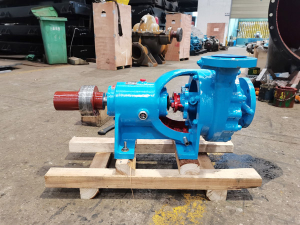
N-type / NBA-type Horizontal Condensate Centrifugal Pump
Classification:
End Suction Centrifugal Pump
Electric Power Industry
Metallurgical Industry
Energy-saving Renovation
Key words:
Centrifugal Pump
Condensate Pump
Horizontal Centrifugal Water Pump
Hotline:
- Product Description
- Performance Parameter
- Installation Drawings
- Installation And Use
- Faults And Solutions
-
- Commodity name: N-type / NBA-type Horizontal Condensate Centrifugal Pump
Flow Range: 5-137 m³/h</br> Head Range: 12-170 m</br> Power: 3-75 kw</br> NPSH: 0.65-10.3 m</br></br></br></br></br></br>
Product Description
N, NB, NBA type pump are single-stage single-suction cantilever centrifugal condensate pumps. Models GN and GNL are two-stage single-suction centrifugal condensate pumps. They are mainly used in power plants to deliver condensate water from condensers, and serve 750~3000 kW turbo-generator sets for condensate water transportation, as well as conveying other liquids with physical and chemical properties similar to water.
Overview
N, NB, NBA type are are single-stage single-suction cantilever centrifugal condensate pumps. Featuring excellent suction performance, they are applied to deliver condensate water in thermal power plants. The liquid temperature shall not exceed 80℃, and the pump inlet pressure shall not be higher than 0.6 MPa.
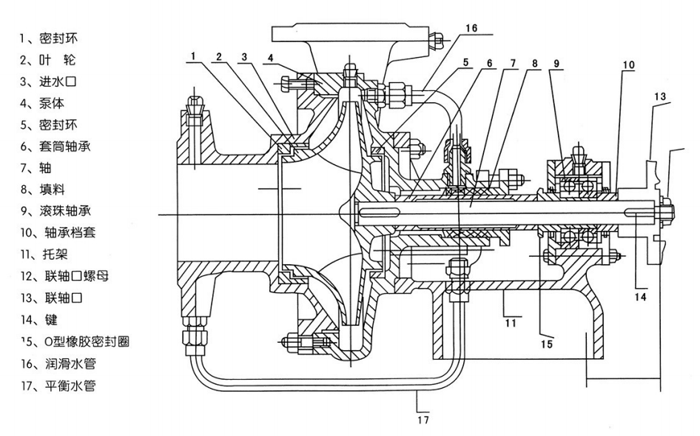
Structure Description
N, NB, NBA, GN type are horizontal type, while Model GNL is vertical type. The pump is equipped with rolling bearings lubricated by grease. Shaft seal adopts packing seal, and mechanical seal is also available as an alternative.
Rotation Direction: Viewed from the motor end, the pump rotates counterclockwise.
Material of Main Components: The wetted parts including pump casing, pump cover, wear ring and shaft sleeve are made of cast iron. For Model N condensate pump, the impeller is silicon brass and the inducer is aluminum iron bronze. All pump shafts are manufactured from high-quality carbon steel.
Scope of Supply: Complete set including pump, motor, coupling, check valve and gate valve.
Application
It is suitable for condensing secondary steam generated during evaporation and concentration of various materials, and is widely used in research laboratories, industrial production and other fields.
Model Description
Example: 100N-45
100 -- Pump inlet diameter (mm)
N -- Condensate pump
B -- Bracket type
45 -- Designed head of the pump (m)
-
Flow Range: 5-137 m³/h
Head Range: 12-170 m
Power: 3-75 kw
NPSH: 0.65-10.3 m
-
-
Pump Installation
1. Check the pump and motor after unpacking. If it is confirmed that there is no damage and loosening of fastening connectors caused by loading, unloading and transportation, the inlet and outlet covers of the pump are intact, and no dirt enters the pump, it can be directly sent to the use site for installation.
2. The foundation plane on which the pump is installed shall be leveled with a level gauge. After the foundation cement is solidified, the pump shall be installed on the foundation and the base shall be corrected with a level gauge. The concentricity of the pump shaft and the motor shaft shall be strictly checked. The tolerance for excircle offset of the coupling shall be 0.1mm. The difference between the maximum and minimum clearance between the end faces of the two couplings shall not exceed 0.3mm.
3. The suction pipeline and the pressure-out pipeline of the pump should be supported. The weight of the pipeline is not allowed to be directly borne by the pump. Check whether the pipeline, instrument and other interfaces are sealed well.
Pump Operation
1. Start-up
1). Prepare necessary tools.
2). Check the oil level in the bearing housing oil reservoir. Keep the oil level around 2 mm from the center line of the oil level gauge.
3). Verify that the rotation direction of the motor matches that of the pump. Reverse rotation is strictly prohibited.
4). Rotate the coupling manually. The rotation shall be smooth and even. Listen for abnormal noises such as friction or rolling foreign objects inside the pump, and eliminate faults if any.
5). Close the gate valve on the discharge pipeline and the outlet pressure gauge. Vent air completely and fully fill the pump and suction pipeline with liquid.
6). When the liquid temperature exceeds 80℃, preheat the pump evenly by feeding high-temperature process liquid into the pump casing. Open all cooling water pipes and drain cocks for the seal chamber, and check the flow and temperature conditions.
7). Start the motor (inching is recommended first to confirm correct rotation before formal operation). Turn on the inlet and outlet pressure gauges, then slowly open the discharge gate valve to the required opening, and adjust the seal chamber drain cock to a proper position.
2. Running
1). Regularly monitor the temperature rise of the pump and motor. The temperature rise of bearings shall not exceed 35℃, and the maximum operating temperature shall not exceed 75℃.
2). Keep the oil level in the bearing housing within the specified range at all times. Replace lubricating oil periodically according to on-site operating conditions to ensure oil cleanliness and effective lubrication.
3). Maintain slight dripping leakage at the packing gland.
4). Shut down the pump immediately if abnormal noise or other faults occur during operation. Do not restart until all faults are rectified.
5). Never regulate flow by closing the gate valve on the suction pipeline, to avoid cavitation.
3. Shutdown
1). Slowly close the discharge gate valve, then stop the motor.
2). Turn off the inlet and outlet pressure gauges, and drain all liquid from the pump.
3). Close the cooling water valves after the pump cools down.
4). For long-term shutdown, drain all liquid and thoroughly clean the pump, especially the seal chamber. It is recommended to disassemble, clean and reassemble the pump, apply anti-rust oil, seal the pump inlet and store the unit properly.
-
1. Pump fails to draw water; needles of pressure gauge and vacuum gauge fluctuate violently.Causes: Insufficient priming water; air leakage from pump or instruments.Solutions: Refill water into the pump; fasten fittings or block air leakage points.
2. Pump fails to draw water, and vacuum gauge indicates high vacuum.Causes: Suction pipeline closed or blocked; excessive suction resistance; suction lift exceeding the allowable limit.Solutions: Inspect the suction pipeline; clean or replace the suction pipe; reduce the suction lift.
3. Pressure is indicated on the discharge side while no water is delivered.Causes: Excessive resistance of discharge pipeline; wrong rotation direction; clogged impeller; insufficient pump speed.Solutions: Inspect or shorten the discharge pipeline; correct motor rotation direction; clean the impeller; increase pump shaft speed.
4. Actual flow rate is lower than rated value.Causes: Pump clogging; severe wear of wear ring; insufficient rotating speed.Solutions: Clean the pump and pipelines; replace the wear ring; increase pump shaft speed.
5. Excessive power consumption.Causes: Over-tight packing gland; worn impeller; excessive water delivery flow.Solutions: Loosen the packing gland or rearrange the packing; replace the impeller; adjust the gate valve to reduce flow rate.
6. Abnormal noise occurs during operation, flow drops until no water is discharged; premature wear of balancing device.Causes: Gate valve fully opened; excessive suction pipeline resistance; air ingress at suction side; excessive suction lift; overhigh temperature of conveyed liquid.Solutions: Adjust the gate valve to cut down flow rate; inspect suction pipeline and foot valve; reduce suction lift; fasten or block leakage points; lower liquid temperature.
7. Pump vibration.Cause: Misalignment between pump shaft and motor shaft.Solution: Realign the center lines of pump shaft and motor shaft.
8. Overheated bearing.Causes: Lack of lubricant or contaminated oil; misalignment of pump shaft and motor shaft.Solutions: Refill or replace lubricating oil; realign the two shafts.
Previous Page
Customer Case
Product Consulting
If you are interested in our products, please leave your email, we will contact you as soon as possible, thank you!


Hunan Sanchang Pump Co., Ltd.
| Email: | info@sanchangpump.net |
| Hotline: | +86 181 4266 2779 |
| +86 193 1300 1794 | |
| Mobile/Wechat/WhatsApp: | +86 181 4266 2779 |
| Address: | No.517,Xiangfu Road, Yuhua |
| District, Changsha City | |
| Hunan Province, P.R.C |
