
Recommend Products
Contact Us
| Email: | info@sanchangpump.net |
| Hotline: | +86 181 4266 2779 |
| +86 193 1300 1794 | |
|
Wechat: |
+86 181 4266 2779 |
|
WhatsApp: |
+86 181 4266 2779 |
| Address: | No.517,Xiangfu Road |
| Yuhua District, | |
| Changsha City | |
| Hunan Province, P.R.C |

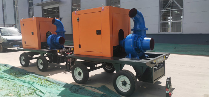
HW Type Diesel Engine Driven Mobile Emergency Pump
Classification:
Mixed Flow Pump
HW horizontal mixed-flow pump
Water Conservancy Industry
Key words:
Diesel Engine Driven Pump
Mobile Emergency Pump
Water Pump
Hotline:
- Product Description
- Performance Parameter
- Installation Drawings
- Installation And Use
- Faults And Solutions
-
- Commodity name: HW Type Diesel Engine Driven Mobile Emergency Pump
Flow Range: 90-9000 m3/h</br> Head Range: 3.5-22 m</br> Matched power: 3-250 kw</br></br></br></br></br></br></br></br>
Product Description
HW type mixed flow pump is horizontal mixed flow pump. It is designed for conveying clean water and river water, with the liquid temperature not exceeding 50℃. Widely applied in farmland irrigation and drainage, as well as industrial and urban water supply and drainage.
Overview
In terms of flow rate and head, HW type mixed flow pump falls between centrifugal pumps and axial flow pumps. It features compact size, light weight, simple structure, easy operation and convenient maintenance. It is suitable for conveying clean water or media with similar properties, and serves farmland irrigation & drainage and industrial water supply & drainage systems.
Structure Description
1. Features: Simple structure, easy installation and disassembly, high efficiency, compact size and light weight.
2. Transmission mode: Direct drive and variable speed drive. The common prime movers are electric motors and diesel engines. Please specify the model, power and rotating speed of the prime mover when placing orders to confirm the specifications of couplings and pulleys.
3. Rotation direction: Viewed from the pump inlet, the impeller normally rotates counterclockwise.
Application
It is used to deliver clean water or other liquids with physical and chemical properties similar to water, applicable to farmland irrigation and drainage, industrial and urban water supply and drainage, etc.
Model Description
Example: 300HW-7S
300 -- Inlet and outlet diameter of the pump (mm)
HW -- Volute mixed flow pump
7 -- Head (m)
S -- Structural type, split casing with front and rear access covers
This standard HW-S series pump is designed, manufactured and inspected in accordance with GB/T13008 and JB/T6667.
-
Flow Range: 90-9000 m3/h
Head Range: 3.5-22 m
Matched power: 3-250 kw
-
Commissioning
After installation, the mixed flow pump shall undergo trial operation to check its rotation direction and rectify installation defects.
Start-up Procedure
1. Close the outlet gate valve and check valve.
2. Priming: Add water through the threaded hole on the top of the pump casing; or open the check valve to let water flow back from the outlet tank for priming; or use a vacuum pump for vacuum priming. Start the pump and stop the vacuum pump once air is fully evacuated and water flows out.
3. After the prime mover runs at rated speed, fully open the gate valve, then adjust the tightness of the packing. Continue operation if the pump runs steadily, bearing temperature is normal and vibration is slight. If a check valve is installed, lift the valve disc after water discharge to reduce flow resistance.
Operation and Maintenance
1. For bearings with oil lubrication, always keep the oil level between the two marks on the oil level gauge. For grease-lubricated bearings, replenish grease regularly. For 100\350 HW pumps, remove the front and rear covers for grease filling; for 400\650 HW pumps, replenish grease via the grease cup.
2. Routinely check bearing temperature rise. The temperature rise shall not exceed 40 ℃ above ambient temperature, and the maximum operating temperature shall not exceed 80 ℃.
3. Listen for friction or knocking noise during operation. If friction occurs between the pump cover and impeller, add paper gaskets between them. The practical clearance shall be kept within 0.3~0.7 mm.
4. Adjust the packing to a proper tightness. Liquid shall drip intermittently from the packing gland. Over-tight packing will cause shaft overheating and increased power consumption; over-loose packing leads to excessive liquid leakage and reduced efficiency.
5. For direct-coupled motor and pump units, ensure perfect shaft alignment.
6. Inspect the suction pipeline for air leakage regularly.
7. Watch out for abrupt change of power or sharp drop of flow rate. Stop the pump immediately and troubleshoot if any abnormal conditions occur.
8. Check all bolts regularly to prevent loosening caused by vibration.
9. In winter, drain all residual water inside the pump and pipelines after shutdown.
10. Replace lubricating oil or grease after the initial 200 operating hours or half a year of service. Thereafter, perform oil/grease replacement every 1000 operating hours or every year.
11. Dismantle, inspect and maintain the pump after 3000 operating hours or three years of service.
12. For long-term idle pumps, disassemble rotating components, apply anti-rust treatment and store them properly.
-
Overheating of Drive Shaft or Motor Bearings
The main causes include insufficient lubricant or damaged bearings. This fault can be fixed by refilling lubricant or replacing the bearings.
No Water Discharge
Three common causes: the pump casing and suction pipe are not fully primed; the dynamic water level is below the strainer pipe; the suction pipe is cracked.
Solutions: Troubleshoot the foot valve and complete priming; lower the pump mounting position to submerge the strainer pipe, or resume pumping after the water level rises above the strainer; repair or replace the damaged suction pipe.
Excessive Power Consumption
Causes of excessive power consumption: excessive pump speed, bent pump shaft, misaligned or non-parallel shafts between pump and motor, improperly selected pump head, sediment or foreign blockages inside the pump, and damaged motor ball bearings.
Causes of severe vibration and abnormal noise: unstable installation or excessively high mounting position of the pump, damaged motor ball bearings, bent pump shaft, as well as misaligned or non-parallel shafts of pump and motor.
Solutions: Secure the pump firmly or reduce its mounting height; replace faulty motor ball bearings; straighten the bent pump shaft or realign the pump and motor shafts.
Insufficient Flow Rate
Main causes: air leakage from the suction pipe or foot valve; blocked pump inlet; insufficient submergence depth of the foot valve; low pump speed; severe wear of wear rings or impeller; suction lift exceeding the allowable limit.
Solutions: Inspect the suction pipe and foot valve to eliminate air leakage; clear sludge and blockages at the pump inlet; ensure the submergence depth of the foot valve is no less than 1.5 times the diameter of the suction pipe and increase the depth if needed; check the power supply voltage to raise pump speed, and replace worn wear rings or impeller; lower the pump installation position or replace it with a mixed flow pump of higher head.
Previous Page
Next Page
Customer Case
Product Consulting
If you are interested in our products, please leave your email, we will contact you as soon as possible, thank you!


Hunan Sanchang Pump Co., Ltd.
| Email: | info@sanchangpump.net |
| Hotline: | +86 181 4266 2779 |
| +86 193 1300 1794 | |
| Mobile/Wechat/WhatsApp: | +86 181 4266 2779 |
| Address: | No.517,Xiangfu Road, Yuhua |
| District, Changsha City | |
| Hunan Province, P.R.C |
