
Recommend Products
Contact Us
| Email: | sales@sanchangpump.com |
| Hotline: | +86 133 0748 1676 |
| +86 193 1300 1794 | |
| Mobile: | +86 133 0748 1676 |
| Wechat: | +86 193 1300 1794 |
| Address: | No.517,Xiangfu Road |
| Yuhua District, | |
| Changsha City | |
| Hunan Province, P.R.C |

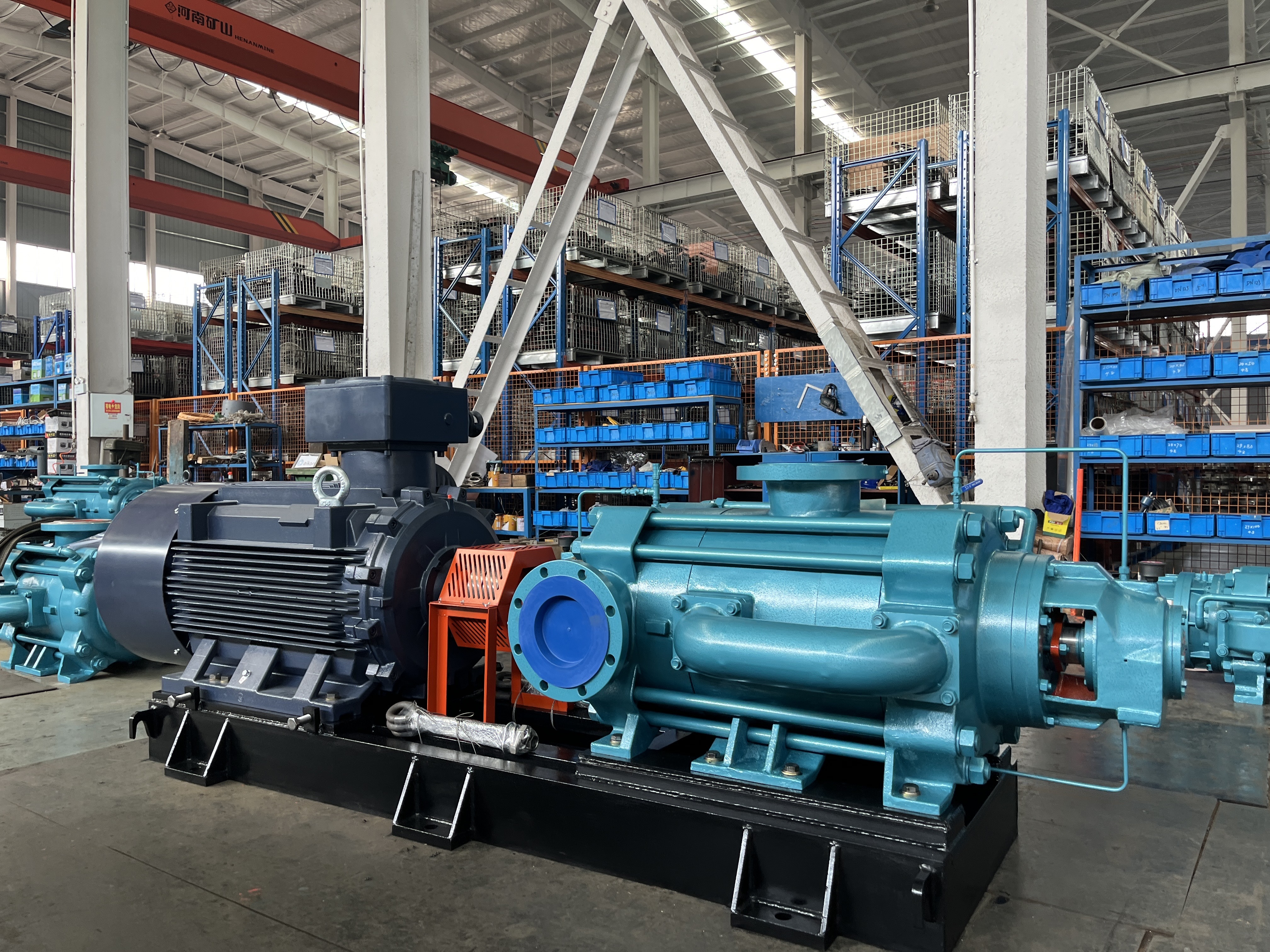
DP type self-balancing horizontal multistage centrifugal pump
Classification:
BB4 Self-balancing Multistage Pump
DP horizontal multistage centrifugal pump
Mining industry
Multi-stage pump for mine
Key words:
water pump
Head range: 50~2000m
Conveying temperature: 0 ℃ ~ 80 ℃
Inlet pressure: allowable inlet pressure 0.6MPa
Sealing form: packing seal, mechanical seal
Water pump material: HT200, HT250, QT600, ZG, 304, 316, 316L, 317L, 904L, CD4-MCu, etc
Hotline:
- Product Description
- Performance Parameter
- Installation Drawings
- Installation And Use
- Faults And Solutions
-
- Commodity name: DP type self-balancing horizontal multistage centrifugal pump
Flow range: 3.75~1400 m3/h<br>Head range: 50~2000m<br>Conveying temperature: 0 ℃ ~ 80 ℃<br>Inlet pressure: allowable inlet pressure 0.6MPa<br>Sealing form: packing seal, mechanical seal<br>Water pump material: HT200, HT250, QT600, ZG, 304, 316, 316L, 317L, 904L, CD4-MCu, etc</br></br></br></br></br>
D(P) type self-balancing multistage pump is my company in the introduction, digestion, absorption of advanced technology on the basis of successful research and development, the product is not only high efficiency, good cavitation performance, the key is stable and reliable operation. It is suitable for coal, mines, factories and other occasions to transport neutral mine water and other similar sewage with solid particle content not more than 1.5 (particle size less than 0.5mm) and temperature not more than 40 ℃.
Model Description
Example: D280J-43X8(P);
D(P)-energy-efficient self-balancing multistage pump;
280-flow at design point (m3/h);
J-mechanical seal (not marked as packing seal);
43-Single stage head of pump at design point (m);
8-The number of stages of the pump is 8.
Structure and working principle of main components
1. Main parts
Forward water section, water outlet section, rear water inlet section, guide vane, right guide vane, left guide vane of water outlet section, right guide vane of water outlet section, middle section, impeller, right impeller, shaft, balance drum, front positioning sleeve, rear positioning sleeve, connecting frame, reversing flow passage, etc.; the rotor is composed of impeller, right impeller, balance drum, impeller stop sleeve, front positioning sleeve, rear positioning sleeve and other parts installed on the shaft, the drive end of the rotor is supported by a roller bearing, and the end is arranged face to face with a pair of angular contact ball bearings, and the bearings are lubricated with grease.
2 The Studio
It is jointly formed by the forward water section, the rear water inlet section, the middle section, the guide vane, the right guide vane, the left guide vane of the water outlet section, the right guide vane of the water outlet section, the reversing flow channel and the water outlet section. The liquid enters along one side of the axial direction. When working, the axial forces acting on each pair of symmetrically arranged impellers are opposite and can offset each other, so that the generated axial forces are balanced, the low pressure stage is arranged at both ends to reduce the pressure on the shaft seal.
3. Seals
① shaft seal: the use of soft packing seal, packing the degree of tightness must be appropriate to the liquid can be a drop of a drop of leakage is appropriate.
② Transmission: the pump is directly driven by the motor through the elastic coupling; from the direction of the motor, the pump rotates clockwise.
③Bearing: The driving end adopts roller bearings, and the end adopts a pair of angular contact ball bearings.
④ Seal ring: prevent the high pressure water in the pump from leaking back to the water inlet, and can be replaced after wear.
⑤ Balance drum: installed after the last stage impeller, it rotates with the rotor, and the outer surface of the balance drum and the inner hole surface of the balance sleeve form a radial gap.
⑥ Front and rear positioning sleeves: at the two packing chambers, they can be replaced after wear.
4. Working principle
The pump shaft rotates under the drive of the motor to work on the liquid to increase its energy, so that the required amount of liquid is sent to the required height or the required pressure by the suction pool through the flow component of the pump.
Product Features
(1) The operation is trouble-free and the overhaul period is long. The unique axial force balance method and the "solid-swimming" bearing positioning can effectively prevent the occurrence of mechanical friction and collision during operation, ensure trouble-free operation, and increase the overhaul cycle.
(2) The water pump has high efficiency and good energy saving effect. The use of new advanced sealing technology greatly reduces leakage losses, improves pump efficiency, and achieves energy-saving effects.
(3) Adopt new structures and integrate new technologies. The symmetrical arrangement of the impeller breaks through the traditional structure mode of the pump, and the unique throttle, decompression device and balance structure design are more suitable for the occasion of harsh media.
(4) Good cavitation performance and long service life. The first stage impeller adopts double suction structure, which makes the pump have good anti-cavitation performance, smooth operation, low noise and long service life.
(5) Low maintenance cost and long service life. The balance plate which is easy to wear and failure is canceled, and the maintenance cost is greatly reduced. The use of new materials, new technology, new structure to ensure the life and reliability of the operation.
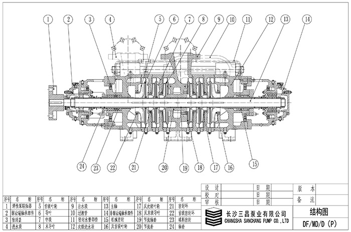
Structure Description
Type D(P) pump is a horizontal balanced structure centrifugal pump. Its suction inlet is in the horizontal direction at the inlet section and its outlet is vertically upward at the outlet section. Tension bolts are used to connect the inlet section, middle section, outlet section and secondary inlet section of the pump into a whole. If the lift is changed, the number of pump stages can be increased or decreased.
1. Main parts of the pump: inlet section, inlet end cover, inlet baffle, middle section, outlet section, secondary inlet section, guide vane, final guide vane, anti-guide vane, final anti-guide vane, impeller, anti-impeller, shaft, throttling and decompression device, stop sleeve, bearing body, transition pipe, etc;
2. The working chamber of the pump is composed of inlet section, middle section, outlet section, secondary inlet section, guide vane, anti-pilot vane and transition pipe;
3. The rotor part is mainly composed of shaft, impeller, reverse impeller, throttling and decompression device, bearing stop sleeve and shaft sleeve. The shaft transmits the power to the impeller to make it work; the bearing adopts the dry oil lubrication structure of "one end fixed, one end swimming bearing group", that is, the driving end adopts cylindrical roller bearing, and the end adopts a pair of angular contact ball bearings;
4. The shaft seal adopts packing seal, which is mainly composed of sealing box body, packing and packing ring on water inlet section and packing box body. The liquid in the sealed working chamber plays the role of water seal, water cooling and water lubrication. Water seal water comes from internal pressure water of pump or external pressure water. Both ends of the shaft are equipped with replaceable shaft sleeves to protect the shaft.
-
Flow range: 3.75~1400 m3/h
Head range: 50~2000m
Conveying temperature: 0 ℃ ~ 80 ℃
Inlet pressure: allowable inlet pressure 0.6MPa
Sealing form: packing seal, mechanical seal
Water pump material: HT200, HT250, QT600, ZG, 304, 316, 316L, 317L, 904L, CD4-MCu, etc
-
-
Preparation before 1. installation
1. Determine the installation location of the multi-stage pump: the location where the installation is stable and easy to operate, repair and overhaul should be selected.
2. Confirm the location of the water injection port: the water injection port should be set at the inlet pressure pipe and about 20cm away from the pump to avoid backflow and change the impeller speed of the multi-stage pump.
3. Deal with the inlet pressure pipeline: prepare the pipeline and flange connection part to ensure that the connection part is free of foreign matter or rust.
4. Prepare the power supply and cables: select the appropriate cable according to the power requirements of the multi-stage pump, and ensure that the cable quality is good.
2. installation steps
1. Assemble the components: Assemble the components according to the requirements of the instructions or drawings, and determine the positions of the drain, vent, and lubrication parts.
2. Install the multi-stage pump: place the multi-stage pump in the installation position, pay attention to the smooth contact between the base of the multi-stage pump and the ground, and the seat surface of the base is perpendicular to the ground.
3. Interface connection: connect the inlet pressure pipe and the outlet pressure pipe. The connecting flange shall be parallel and horizontal without distortion and deformation.
4. cable wiring: according to the multi-stage pump electrical connection diagram wiring, pay attention to the standardization of wiring and reasonable wiring.
5. Water injection and drainage: open the stop valve of the inlet pressure pipe of the multi-stage pump, and introduce clean water (or including the added pump irrigation and drainage liquid) into the pump to avoid abnormal noise caused by pump vibration.
6. Adjust the pump: adjust the frequency converter or on-demand reducer to ensure that the motor of the multi-stage pump works normally and the water flow speed is moderate.
Inspection after 3. installation
1. Check the overall installation of the pump: to ensure that the base of the multi-stage pump is stable and vertical.
2. Check the connection of each pipeline: confirm whether each interface is tightly connected and whether there are abnormal conditions such as abnormal noise.
3. Pump movement test: turn on the power, check whether the motor rotation is stable, whether the sound is normal, whether the pump is leaking, etc.
4. System pressure test: In the experiment, the intelligent instrument records data such as the opening and closing state of the control valve and the water flow. During the test, pay attention to whether there are abnormal conditions such as noise, vibration or high temperature around the system, and deal with any abnormalities in time.
5. Check the wires: Confirm whether the wires are correctly wired and free of damage and other relevant details meet the installation specifications.
The above is a detailed explanation of the installation steps of the multi-stage pump. I hope readers can install the multi-stage pump correctly according to the above steps to ensure that the installed multi-stage pump can operate normally and provide better protection for production and life.
-
Fault one: multi-stage pump does not absorb water pressure gauge and vacuum gauge pointer beating violently
Cause: 1. Insufficient water injection and diversion 2. Air leakage at the connection between pipeline and instrument 3. Excessive suction
Solution: 1. Check whether the bottom valve leaks. 3. Lower the suction height
Fault two: multi-stage pump does not absorb water vacuum table indicates a high degree of vacuum
Reason: 1. The bottom valve is not opened or blocked 2. The resistance of the suction pipeline is too large 3. The filter is blocked
Solution: 1. Check the bottom valve 2. Replace the water absorption 3. Clean the filter
Fault three: pressure gauge pressure but still not out of water
Reason: 1. The resistance of the outlet pipe is too large 2. The rotation direction is wrong 3. The outlet pipe valve is not open 4. The impeller is blocked
Solution: 1. Check or short water pipe 2. Check the motor. Two-phase intermodulation 3. Open the outlet valve 4. Remove the dirt in the impeller
Fault four: can not reach the design flow
Reason: 1. air inhalation 2. due to the lowering of the water level. The submerged depth is not enough. 3. The impeller is blocked by foreign matter. 4. The rotor is severely worn.
Solution: 1. Check the air leakage site and exclude 2. Extend the suction pipe. Deepen the flooding depth 3. Remove and remove foreign objects 4. Replace the sealing ring
Fault five: multi-stage pump power consumption is too large
Reason: 1. Packing is too tight. And heat 2. The flow is too large 3. The rotating body and the shell rub 4. The pump bearing is worn 5. The pump shaft is bent.
Solution: 1. Relax the packing pressure appropriately 2. Close the gate valve opening 3. Trim the position of the rotary body and the shell 4. Replace the bearing 5. Replace or correct
Fault six: multi-stage pump vibration increased
Reason: 1. The impeller is partially blocked 2. The impeller is damaged 3. The flow rate is too small 4. The pump shaft is not concentric with the motor 5. The bearing is damaged 6. Air is mixed. Cavitation occurs
Solution: 1. Disassemble and remove foreign matter 2. Replace the impeller 3. Slightly open the outlet valve 4. Point aligning 5. Change the suction position. Improved water absorption
Customer Case
Product Consulting
If you are interested in our products, please leave your email, we will contact you as soon as possible, thank you!


Hunan Sanchang Pump Co., Ltd.
| Email: | sales@sanchangpump.com |
| Hotline: | +86 133 0748 1676 |
| +86 193 1300 1794 | |
| Mobile/wechat: | +86 133 0748 1676 |
| +86 193 1300 1794 | |
| Address: | No.517,Xiangfu Road, Yuhua |
| District, Changsha City | |
| Hunan Province, P.R.C |
