
PRODUCTS CENTER

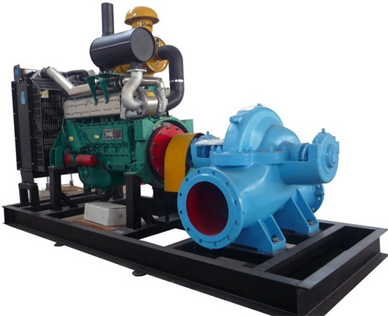
BIH Diesel-engine Double-suction Split Casing Centrifugal Pump
Product Description
Our R&D team develops this pump based on mature similar products.It adopts an innovative structural design.This is a horizontal single-stage horizontally split pump.
It transports media with physical and chemical properties close to clean water.The medium temperature limit is 80°C.
Common application scenarios:
- Industrial process water supply
- Fire fighting systems
- Urban flood control and drainage
I. Model Description
Example: 500 S 35A
- 500 —— Pump inlet diameter: 500 mm
- S —— Single-stage, double-suction, split-case clean water centrifugal pump
- 35 —— Design head: 35 m
- A —— First trimming of the impeller
II. Transmission Modes
Two drive options are available: direct drive and variable speed drive.
Please provide the following data before placing orders:Motor model, power and rotating speed.
We will confirm matching coupling or pulley specifications accordingly.
III. Rotation Direction
Viewed from the pump side, the pump rotates counterclockwise.
Ⅳ. Material Description
Optional component materials:
Copper, Cast Iron, Ductile Iron, 304 Stainless Steel, 316 Stainless Steel, 416 Stainless Steel, Duplex Steel, Hastelloy, Monel, Titanium Alloy, Alloy 20
Ⅴ. Operating Conditions
1. Ambient temperature ≤ 50°C; conveyed medium temperature ≤ 80°C.
2. For cast iron pumps, the pH value of the medium shall range from 6 to 9.
3. Maximum density of the conveyed medium: 1240 kg/m³.
4. A foot valve shall be installed and the pump shall be primed. Maximum suction lift ≤ 6 m; maximum suction pipe length ≤ 10 m.
Ⅵ. Performance Features
1. Easy Maintenance & Custom Rotation
- Suction and discharge nozzles sit under the pump shaft centerline, perpendicular to the shaft.
- No pipeline disconnection or motor removal is needed for maintenance.
- Standard rotation: counterclockwise (viewed from pump drive end).
- Custom rotation directions are available upon request.
2. Main Parts & Material Options
- Core components: pump casing, pump cover, impeller, shaft, double-suction wear ring, shaft sleeve
- Pump shaft material: carbon steel
- Other parts: cast iron, cast steel or stainless steel
3. Pump Casing & Pump Cover
- The casing and cover form the impeller working chamber.
- Flanges have reserved threaded holes for vacuum gauges and pressure gauges.
- Threaded drain holes are set at flange bottoms to drain residual liquid.
4. Impeller Structure
- All impellers pass static balance testing.
- Sleeve nuts fix the impeller to the pump shaft.
- Adjust the nuts to change the impeller’s axial position.
- Symmetrical double-sided inlet blades automatically balance axial force.
5. Bearing Assembly
- Radial bearings are installed in two end bearing housings.
- They guarantee stable pump running.
- Grease lubrication is adopted for bearings.
6. Double-suction Wear Ring
This part reduces liquid backflow from the pressure chamber to the suction chamber.
7. Drive Forms
- Standard drive: motor connected via coupling
- Optional drive: internal combustion engine (customizable on demand)
8. Shaft Seal System
- Seal selection
Standard: soft packing seal
Optional upgrade: mechanical seal
- Packing ring function
A packing ring is placed between packing rings.
It blocks air intake, and cools & lubricates the seal chamber.
- Water seal working principle
Trapezoidal grooves are machined on the pump cover split face.
A small stream of high-pressure liquid flows through these grooves into the seal chamber.
This liquid forms a water seal during pump operation.



Hunan Sanchang Pump Co., Ltd.
| Email: | info@sanchangpump.net |
| Hotline: | +86 181 4266 2779 |
| +86 193 1300 1794 | |
| Mobile/Wechat/WhatsApp: | +86 181 4266 2779 |
| Address: | No.517,Xiangfu Road, Yuhua |
| District, Changsha City | |
| Hunan Province, P.R.C |
